
8 ITEMSVIEW CART


Total: 2,360.00
Expert Support
Full Speed
100% Working
15 USD
Contents:
Section 1 – Platform Parts
1.1 Platform
1.2 Railings
1.3 Platform Base (Ansi/Csa)
1.4 Platform Base (Ce & As)
1.5 Swing Gate (A)
1.6 Swing Gate (B)
1.7 Drop Bar Gate (A)
1.8 Drop Bar Gate (B)
1.9 Railing Extension (No Gate)
1.10 Footswitch
1.11 Platform Control Console
1.12 Boom / Turret Controller (Dual Axis)
1.13 Drive / Steer Controller (Single Axis)
1.14 Platform Terminal Strip
Section 2 – Boom Parts
2.1 Boom Assembly
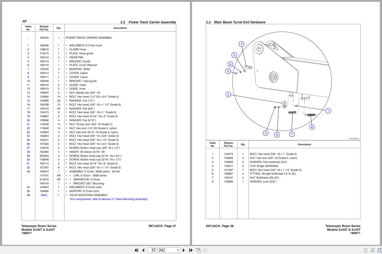
2.2 Power Track Carrier Assembly
2.3 Main Boom Turret End Hardware
2.4 Main Boom Platform End Hardware
2.5 Fly Boom Platform End Hardware
2.6 Extension Cylinder Support Assembly
2.7 Valve Mounting Assembly
2.8 Work And Travel Limit Switch Mounting Assembly (Universal)
2.9 Jib Assembly – Sj45t
2.10 Rotary Actuator Mounting – Sj40t
2.11 Rotary Actuator Assembly
2.12 Jib Lift / Platform Rotate Valve Assemblies
Section 3 – Cylinders
3.1 Lift Cylinder Assembly
3.2 Extension Cylinder Assembly
3.3 Master Cylinder Assembly
3.4 Slave Cylinder Assembly
3.5 Jib Cylinder Assembly
3.6 Axle Lockout Cylinder Assembly
Section 4 – Turret Parts
4.1 Cowling Assembly – Engine Side
4.2 Cowling Assembly – Controls Side
4.3 Cowling Assembly – Centre
4.4 Counterweight Assembly
4.5 Turret Assembly
4.6 Lift Cylinder Bracket Assembly
4.7 Main Boom Pin Assembly
4.8 High Pressure Filter Assembly
4.9 Turret Swing Drive Assembly
4.10 Main Manifold Assembly
4.11 Brake Control Valve Assembly
4.12 Rotary Manifold
4.13 Rotary Manifold Propane Fittings (Gm Engine)
4.14 Reducing Valve
4.15 Hydraulic Tank Assembly
4.16 Fuel Tank Assembly (Gm Dual Fuel Engine)
4.17 Fuel Tank Assembly (Deutz D2.9l Engine)
4.18 Fuel Tank Assembly (Deutz D2011 Engine)
4.19 Emergency Power Unit
4.20 Battery Assembly
4.21 Base Control Console (Deutz D2.9l Engine)
4.22 Base Control Console (Deutz D2011 Engine)
4.23 Base Control Console (Gm Dual Fuel Engine)
4.24 Base Terminal Strip (Deutz D2.9l Engine)
4.25 Base Terminal Strip (Deutz D2011 & Gm Engines)
4.26 No Generator And Oil Cooler Hose Fitting
Section 5 – Electrical Harnesses
5.1 Main Electrical Harness
5.2 Cable Harnesses
5.3 Control Cable Harnesses
5.4 Valve Harnesses And Limit Switch Assemblies
5.5 110/220v Outlet Harness
5.6 Ecu Harnesses
5.7 Glow Plug Harness (Deutz D2.9l)
5.8 Glow Plug Harness (Deutz D2011)
5.9 Engine Interface Harness (Deutz D2.9l)
5.10 Engine Interface Harness (Gm Engine)
Section 6 – Base Parts
6.1 Base Assembly
6.2 Axle Assembly Hardware
6.3 Rear Axle Assembly With Gear Box
6.4 Differential Assembly
6.5 Central Housing Assembly
6.6 Gear Box – Rear Axle
6.7 Brakes – Rear Axle
6.8 Front Axle Assembly
6.9 Differential Assembly
6.10 Central Housing Assembly
6.11 Steering Assembly
6.12 Trunnion Assembly
6.13 Axle Drive Shaft
6.14 Propane Tank Assembly
6.15 Tires
Section 7 – Engine Parts
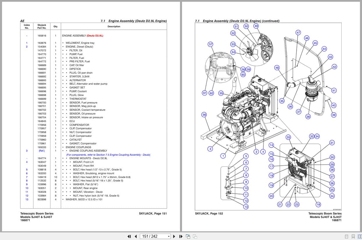
7.1 Engine Assembly (Deutz D2.9l Engine)
7.2 Engine Assembly (Deutz D2011 Engine)
7.3 Drive Pump And System Pump Assembly
7.4 Engine Assembly (Gm Dual Fuel Engine)
7.5 Engine Coupling Assembly – Deutz
Section 8 – Hose Connections
8.1 Standard Hose Numbering System
8.2 Hydraulic Hose Connection – Cylinders
8.3 Hydraulic Hose Connection – Control Compartment
8.4 Hydraulic Hose Connection – Engine Compartment
8.5 Fuel Line Hose Connection – Deutz D2.9l Engine
8.6 Fuel Line Hose Connection – Deutz D2011 Engine
8.7 Fuel Line Hose Connection – Gm Dual Fuel Engine
8.8 Hydraulic Hose Connection – Base And Axles
8.9 Hydraulic Hose Connection – Turret Grease Fittings
Section 9 – Optional Equipment
9.1 Air Hose To Platform Option
9.2 Flashing Amber Light Option
9.3 Generator And Oil Cooler Assembly
9.4 Generator Control Valve Assembly
9.5 110v Generator Cable Assembly (Ansi/Csa)
9.6 Generator And Oil Cooler Harnesses
9.7 Generator Wire Assemblies
9.8 Hydraulic Hoses – Generator And Oil Cooler
9.9 12 Kw Generator Assembly
9.10 Generator Wire Assemblies – 12kw Generator
9.11 Hydraulic Hose Connection – 12kw Generator
9.12 Welder And Mounting Assembly
9.13 Cold Start Assembly
9.14 Arctic Package Assembly
9.15 Cold & Arctic Packages Load Circuit – Deutz D2.9l
9.16 Diesel Scrubber – Deutz D2011 Engine
9.17 External Railing Assembly
9.18 Glazier Rack Assembly
9.19 Sgm Assembly
9.20 Sge Assembly
Section 10 – Labels
10.1 Label Kits
10.2 Labels – Platform Control Console
10.3 Labels – Front And Back
10.4 Labels – Engine Side
10.5 Labels – Controls Side
10.6 Labels – Controls Compartment
10.7 Labels – Engine Compartment
10.8 Labels – Engine Fuel
10.9 Labels – Operator Platform
Section 11 – 11.0 Tables
11.1 Fluids Table
11.2 Boom Grease Locations, Turret And Axle Grease Table
11.3 Boom Grease Locations And Gear Grease Table

REALEASE :
REALEASE :
REALEASE :
REALEASE :

REALEASE :
30.05.2020
REALEASE :
30.05.2020
REALEASE :
REALEASE :
REALEASE :
REALEASE :
REALEASE :
REALEASE :
REALEASE :
REALEASE :
REALEASE :
REALEASE :
 Automotive - Heavy Equipment - Truck & Bus - Forklift - Crane