
0 ITEMSVIEW CART

✓
Expert Support
✓
Full Speed
✓
100% Working
Gradall Excavator XL2200 Operators Parts Service Manual
Size: 32.62 MB
Format: PDF
Language: English
Brand: Gradall
Type of Machine: Telescopic Hydraulic Excavator
Type of Manual: Combined Service Manual, Electrical Schematic, Hydraulic Schematic, Illustrated Parts Manual, Operators Manual, Parts Manual
Model: Gradall XL2200 Telescopic Hydraulic Excavator
30 USD
- Description
Description
List of Files:
XL2200 Combined Service Manual 2460-4142 2006.pdf (447 Pages)
Contents:
2460-4142 XL2200 COMBINED SERVICE MANUAL
OPERATOR INSTRUCTION
29629 XL2200 Owner/Operator Manual
SCHEDULED MAINTENANCE
29630 XL2200 Scheduled Maintenance Manual
HYDRAULIC SYSTEM OPERATION
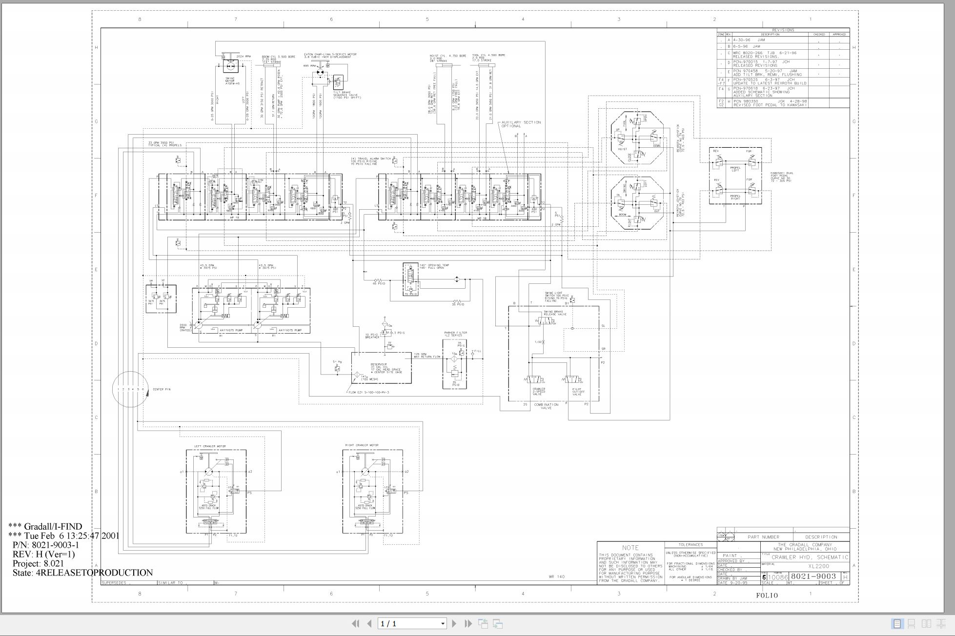
8021-9003 Crawler Hydraulic Schematic
29718 XL2200 Hydraulic System Operations Manual
29805 XL2000 Series Hydraulic Reservoir Return Filter Manual
29801 Hydraulic Swing Pressure Follow-Up Inspection Procedure
29804 Hydraulic Adjustments
MECHANICAL ADJUSTMENTS
29706 XL2200 Boom Adjustment Procedure
75580 Ausco Brake Technical Page
7-116 Char-Lynn Hydraulic Motor Service Manual
29712 Boom Extension Installation
ELECTRICAL
29812 XL2200 Upperstructure Electrical System Manual
1M-128 Delco Remy Cranking Motor Service Manual
8026-9001 Upper Wiring Diagram
8026-3004 Upper Harness
8026-3005 Engine Harness
8026-3013 Seat Harness
8026-3007 Console Assembly
CRAWLER
29635 XL Series Crawler Maintenance Manual
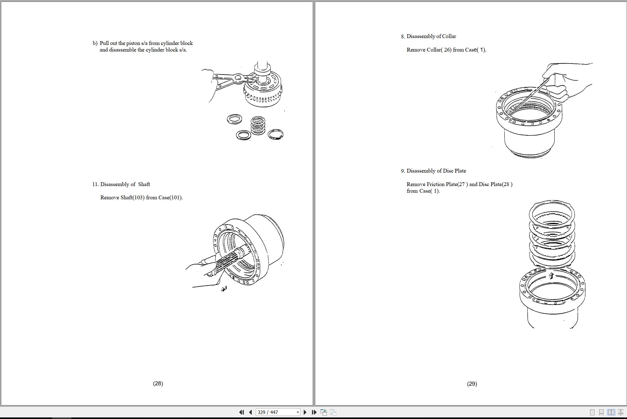
29302 Kayaba Service Manual
MISCELLANEOUS
HE92-2 EMI Safety Manual
20013 Gradall Safety Manual
XL2200 Operators Manual 2460-4143 2002.pdf (48 Pages)
XL2200 Illustrated Parts Manual 24604141 2023.pdf (360 Pages)
Contents:
Service Kits
Section 1 Frame & Attaching Parts
Figure 1-1 Frame Assembly
Figure 1-2 Rotating Platform, R. H. View
Figure 1-3 Rotating Platform, L.H. View
Figure 1-4 Swing Bearing, Cradle & Hoist Cylinder Mounting Pins & Lube System
Section 2 Boom
Figure 2-1 Boom Cradle
Figure 2-2 Main Boom & Roller Assemblies
Figure 2-3 Telescope Boom Assembly
Figure 2-4 Bucket Linkage
Section 3 Attachments
Figure 3-1 18†& 24†Excavating Buckets
Figure 3-2 30†& 36†Excavating Buckets
Figure 3-3 Pavement Removal Bucket
Figure 3-4 60†Ditching Bucket & 60†Ditching Bucket w/Constant Radius
Figure 3-5 60†Ditching Bucket
Figure 3-6 Rammer Bracket Installation
Figure 3-7 Rammer Bracket Installation
Figure 3-8 4’ Boom Extension
Figure 3-9 Fixed Thumb Grapple Assembly
Figure 3-10 Fixed Thumb Grapple
Section 4 Engine & Attaching Parts
Figure 4-1 Engine Assembly, L.H. View
Figure 4-2 Engine Assembly, R.H. View
Figure 4-3 Air Cleaner & Installation
Figure 4-4 Air Cleaner Assembly
Figure 4-5 Exhaust System
Figure 4-6 Fuel Tank Assembly
Figure 4-7 Oil Cooler, Radiator & Hoses
Section 5 Drive Train
Figure 5-1 Track Chain & Shoes
Figure 5-2 Bottom Roller & Carrier Roller
Figure 5-3 Front Idler Track Adjuster Assembly
Figure 5-4 Crawler Drive – Control
Figure 5-5 Crawler Drive – Hydraulic Motor
Figure 5-6 Crawler Drive – Gearbox
Section 6 Cab
Figure 6-1 Operators Cab
Figure 6-2 Cab Door
Figure 6-3 Cab Seat
Figure 6-4 Cab Miscellaneous
Figure 6-5 Cab Heater & Installation
Section 7 Controls
Figure 7-1 Joystick Assembly
Figure 7-2 Foot Pedals & Installation
Section 8 Hydraulic Circuits
Figure 8-1 Oil Supply to Pumps
Figure 8-2 Hydraulic Pressure to Control Valves
Figure 8-3 Hydraulic Hosing to Joystick & Foot Operated Pedal
Figure 8-4 Dump Circuit
Figure 8-5 Hoist Pilot
Figure 8-6 Boom Pilot
Figure 8-7 Tool Pilot
Figure 8-8 Propel Pilot
Figure 8-9 Swing Pilot
Figure 8-10 Swing & Swing Brake
Figure 8-11 Hoist Cylinder
Figure 8-12 Boom Cylinder
Figure 8-13 Tool Cylinder
Figure 8-14 Swing Motor
Figure 8-15 Tilt Motor
Figure 8-16 Upper Propelling
Figure 8-17 Center Pin Hosing
Figure 8-18 Drive Assembly Drain Hoses
Section 9 Hydraulic Components
Figure 9-1 Hoist Cylinder Assembly
Figure 9-2 Boom Cylinder & Tilt Gland Assembly
Figure 9-3 Tool Cylinder Assembly
Figure 9-4 Main Pump – Front
Figure 9-5 Main Pump – Rear
Figure 9-6 Tool, Hoist, Propel & Auxiliary Hydraulic Valve
Figure 9-7 Tool Valve Section
Figure 9-8 Hoist Valve Section
Figure 9-9 Propel Valve Section
Figure 9-10 Auxiliary Valve Section
Figure 9-11 Tilt, Boom, Swing & Propel Valve
Figure 9-12 Tilt Valve Section
Figure 9-13 Boom Valve Section
Figure 9-14 Swing Valve Section
Figure 9-15 Reservoir Assembly
Figure 9-16 Swing Transmission Installation
Figure 9-17 Swing Transmission
Figure 9-18 Swing Motor
Figure 9-19 Swing Brake
Figure 9-20 Tilt Transmission Installation
Figure 9-21 Tilt Transmission
Figure 9-22 Tilt Brake
Figure 9-23 Tilt Motor
Figure 9-24 Center Pin
Figure 9-25 Foot Operated Pedal Valve
Figure 9-26 Thermal By-Pass Valve
Figure 9-27 Clamp Sets & Miscellaneous Hydraulic Components
Figure 9-28 Pump Valve
Figure 9-29 Combination Valve
Section 10 Electrical
Figure 10-1 Batteries & Miscellaneous Electrical Components
Figure 10-2 Cab Console
Section 11 Decals
Figure 11-1 Decals
Section 12 Options
Figure 12-1 Air Conditioner Installation
Figure 12-2 Air Conditioner Installation
Figure 12-3 Air Conditioning Evaporator Kit
Figure 12-4 AM/FM Cassette Stereo Installation
Figure 12-5 Auxiliary Fan Installation
Figure 12-6 Auxiliary Fan Installation
Figure 12-7 Auxiliary Hydraulic Valve Module Installation
Figure 12-8 Auxiliary Hydraulic Valve Field Conversion
Figure 12-9 Additional Battery Installation
Figure 12-10 Cold Start Installation
Figure 12-11 Cold Start Installation
Figure 12-12 Engine Air Precleaner Installation
Figure 12-13 Engine Block Heater Installation
Figure 12-14 Engine Shutdown Installation
Figure 12-15 Engine Shutdown Installation
Figure 12-16 Floodlight Installation
Figure 12-17 Four-Line Hose Trough Installation
Figure 12-18 Lexan Glass Installation
Figure 12-19 Lifting Arrangements
Figure 12-20 Operating Decal
Figure 12-21 Scaling Hook
Figure 12-22 Seat Belt Installation
Figure 12-23 Spark Arrestor Installation
Figure 12-24 Tool Box
Figure 12-25 Vandal Covers Installation
Figure 12-26 Vandal Covers Installation
Figure 12-27 Washer/Wiper Installation
Figure 12-28 Washer/Wiper Installation
Recommended Spare Parts
Part Number Index
XL2200 Hydraulic Schematic 80219003 2001.pdf (1 Pages)
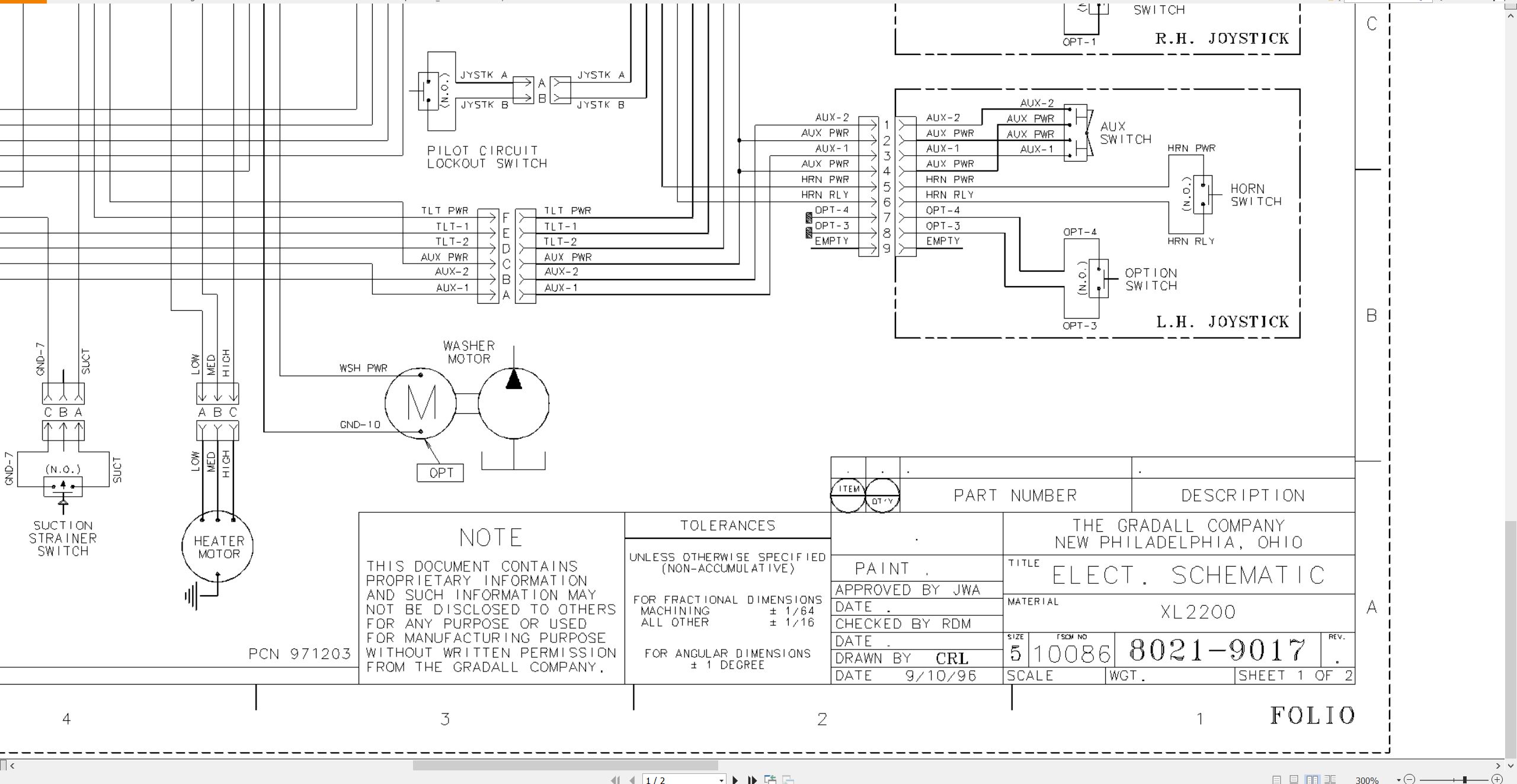
XL2200 Electrical Schematic 80219017 2000.pdf (2 Pages)
Related Products
-
Gradall Wheeled Excavator XL3300V Operators Parts Service Manual
30 USDSize: 214.38 MBFormat: PDFLanguage: EnglishBrand: GradallType of Machine: Rough-terrain Wheeled ExcavatorType of Manual: Electrical Schematic, Hydraulic Schematic, Illustrated Parts Manual, Lubrication Chart, Operator Safety Manual, Parts Manual, Service SupplementModel: Gradall XL3300V Rough-terrain Wheeled Excavator
REALEASE :
REALEASE :
-
Gradall Wheeled Excavator XL4300 Operators Parts Service Manual
30 USDSize: 321.70 MBFormat: PDFLanguage: EnglishBrand: GradallType of Machine: Rough-terrain Wheeled ExcavatorType of Manual: Electrical Schematic, Hydraulic Schematic, Illustrated Parts Manual, Lubrication Chart, Operator Manual, Safety Manual, Parts Manual, Service Manual, Service SupplementModel: Gradall XL4300 Rough-terrain Wheeled Excavator
REALEASE :
REALEASE :
-
Gradall Wheeled Excavator XL4300V Operators Parts Service Manual
30 USDSize: 252.03 MBFormat: PDFLanguage: EnglishBrand: GradallType of Machine: Rough-terrain Wheeled ExcavatorType of Manual: Assembly Manual, Electrical Schematic, Hydraulic Schematic, Illustrated Parts Manual, Installation Instructions, Installation Parts Manual, Lubrication Chart, Maintenance Manual, Operator Manual, Safety Manual, Operators Instruction, Parts Manual, Service Supplement, User ManualModel: Gradall XL4300V Rough-terrain Wheeled Excavator
REALEASE :
REALEASE :
-
Gradall Wheeled Excavator XL5300V Operators Parts Service Manual
30 USDSize: 214.38 MBFormat: PDFLanguage: EnglishBrand: GradallType of Machine: Rough-terrain Wheeled ExcavatorType of Manual: Electrical Schematic, Hydraulic Schematic, Illustrated Parts Manual, Lubrication Chart, Operator Manual, Safety Manual, Parts Manual, Service SupplementModel: Gradall XL5300V Rough-terrain Wheeled Excavator
REALEASE :
REALEASE :
-
Gradall Wheeled Excavator XL5300III Operators Parts Service Manual
30 USDSize: 311.43 MBFormat: PDFLanguage: EnglishBrand: GradallType of Machine: Rough-terrain Wheeled ExcavatorType of Manual: Electrical Schematic, Hydraulic Schematic, Illustrated Parts Manual, Lubrication Chart, Operator Manual, Safety Manual, Parts Manual, Service Manual, Service SupplementModel: Gradall XL5300III Rough-terrain Wheeled Excavator
REALEASE :
REALEASE :
-
Gradall Wheeled Excavator XL5300 Operators Parts Service Manual
30 USDSize: 309.61 MBFormat: PDFLanguage: EnglishBrand: GradallType of Machine: Rough-terrain Wheeled ExcavatorType of Manual: Electrical Schematic, Hydraulic Schematic, Illustrated Parts Manual, Operator Manual, Safety Manual, Parts Manual, Service Manual, Service SupplementModel: Gradall XL5300 Rough-terrain Wheeled Excavator
REALEASE :
REALEASE :
-
Gradall Wheeled Excavator XL4300II Operators Parts Service Technical Manual
30 USDSize: 355.36 MBFormat: PDFLanguage: EnglishBrand: GradallType of Machine: Rough-terrain Wheeled ExcavatorType of Manual: Combined Service Manual, Electrical Schematic, Hydraulic Schematic, Illustrated Parts Manual, Operators Manual, Parts Manual, Service Manual, Technical ManualModel: Gradall XL4300II Rough-terrain Wheeled Excavator
REALEASE :
REALEASE :
-
Gradall Wheeled Excavator XL4300IICE Operators Service Manual 31200155 2006
30 USDSize: 130.81 MBFormat: PDFLanguage: EnglishBrand: GradallType of Machine: Rough-terrain Wheeled ExcavatorType of Manual: Combined Service Manual, Operators Manual, Hydraulic Schematic, Electrical SchematicModel: Gradall XL4300IICE 31200155, XL4300IICE 31200154 Rough-terrain Wheeled ExcavatorSerial Number: 0210017803Part Number: XL4300IICE 31200155, XL4300IICE 31200154Publication Date: 31200155 – 2006, 31200154 – 2005Number of Pages: 953 Pages
REALEASE :
REALEASE :