
6 ITEMSVIEW CART


Total: 325.00
Expert Support
Full Speed
100% Working
30 USD
List of Files:
XL2210 Combined Service Manual 2460-4149 2006.pdf (651 Pages)
Contents:
2460-4149 XL2210 COMBINED SERVICE MANUAL
OPERATION INSTRUCTION
29713 XL2210 Owner/Operator Manual
8021-9004 Start Up Procedure
SCHEDULED MAINTENANCE
20008 XL2210 Scheduled Maintenance Manual
20006 XL2210 Shop & Specifications Manual
HYDRAULIC SYSTEM OPERATION
20009 XL2210 Scheduled Operations Manual
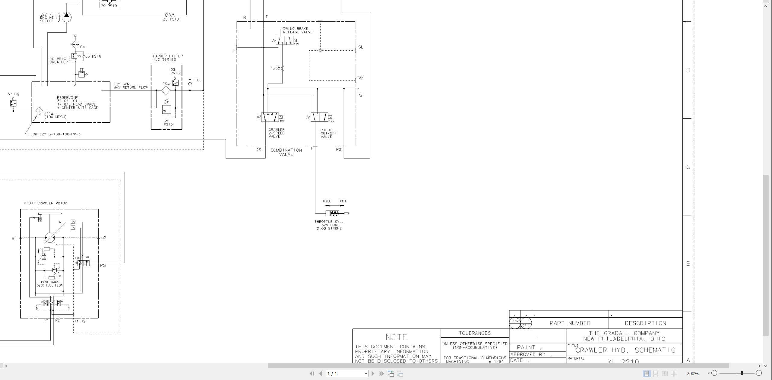
8021-9022 Crawler Hydraulic Schematic
29805 XL2000 Series Hydraulic Reservoir Manual
MECHANICAL ADJUSTMENTS
20010 XL2210 Boom Adjustment Procedure
75580 Ausco Brake Technical Page
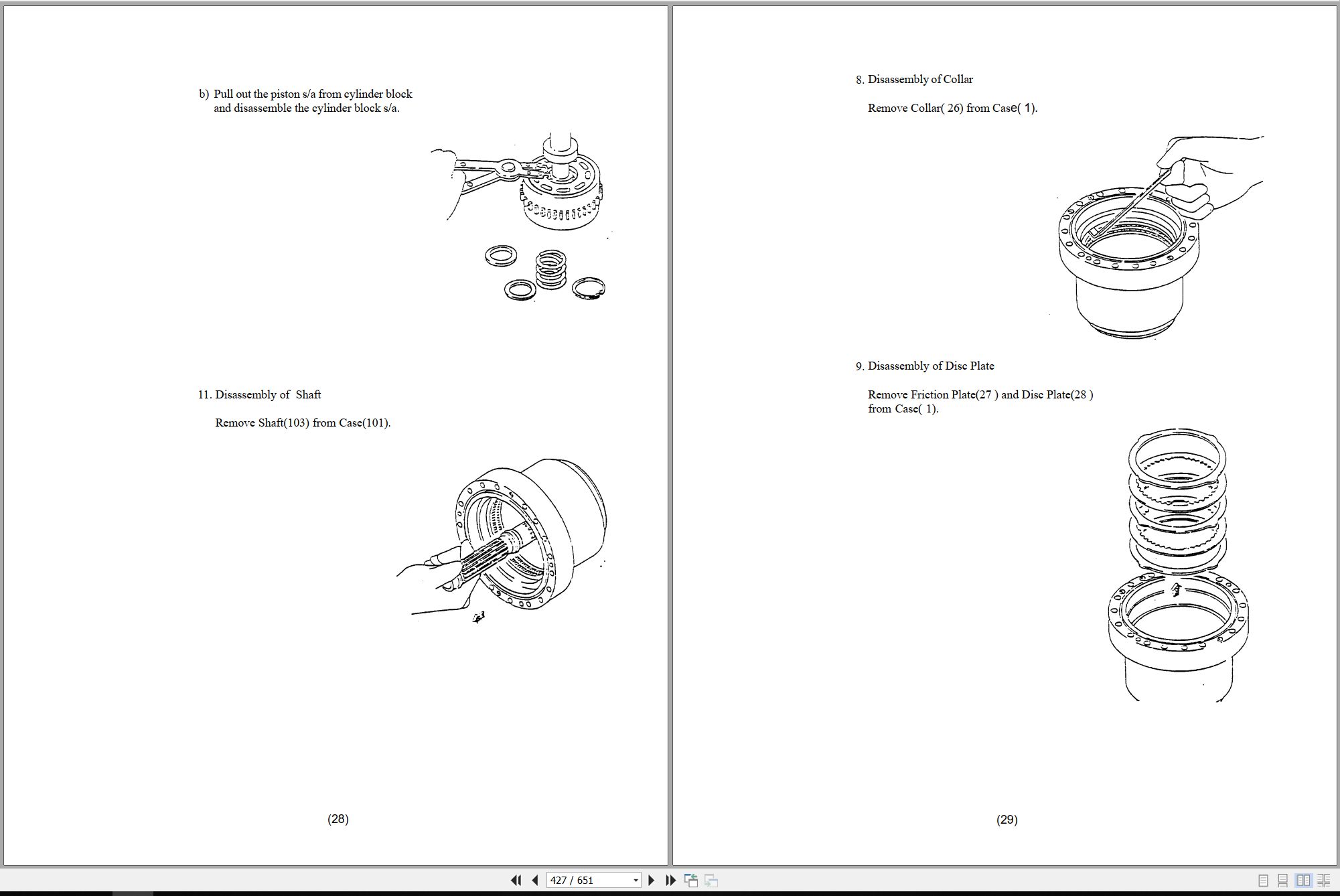
7-116 Char-Lynn Hydraulic Motor Service Manual
29712 Boom Extension Installation
ELECTRICAL
1M-128 Delco Remy Cranking Motor Service Manual
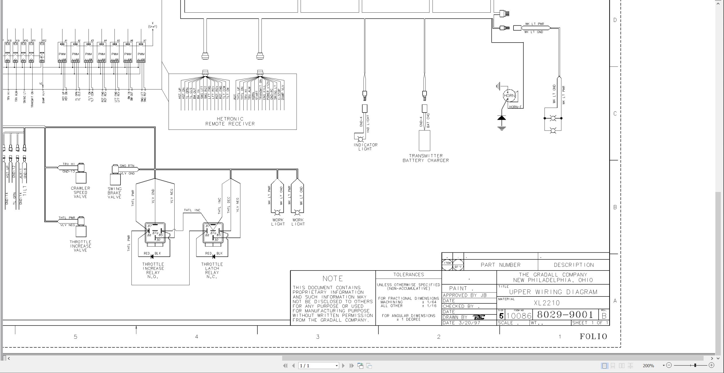
8029-9001 Upper Wiring Diagram
8026-3120 Upper Harness
8026-3077 Engine Harness
8026-3040 Swing Brake Harness
8026-3014 Boom Lights Harness
20012 Hetronic Radio Remote Control System Service Manual
CRAWLER
29635 XL Series Crawler Maintenance Manual
29302 Kayaba Final Drives Service Manual
MISCELLANEOUS
HE92-2 EMI Safety Manual
20013 Gradall Safety Manual
8029-9002 Test Report
8021-4047 S-27 Rammer Hammer Service Manual
XL2210 Operators Manual 2460-4150 2002.pdf (46 Pages)
Contents:
IMPORTANT SAFETY NOTICE
LIST OF EFFECTIVE PAGES (revision info)
INTRODUCTION
General
Related Manuals & Decals
Operator Qualifications
Orientation
PIN Plate Location
Models Covered
Nomenclature
TOOL KIT
SAFETY HIGHLIGHTS
DECALS
SERIAL NO. PLATES
CHECKS & SERVICES BEFORE STARTING ENGINE
REMOTE CONTROLS
General
Control Compartment
Remote Control Transmitter
Electronic Monitor
ENGINE OPERATOR
Starting Engine
Cold Weather Starting Aids
Normal Engine Operation
Stopping the Engine
WARM-UP & OPERATIONAL CHECKS
ADAPTER ATTACHMENT INSTALLATION
USE YOUR CRAWLER PROPERLY
Crawler Controls
How to Operate the Crawler
A TYPICAL GRADALL DIGGING CYCLE
HAMMER INSTALLATION
Installation
Removal
LUBRICATION & MAINTENANCE
Lubrication & Maintenance Diagram & Schedule
Recommended Lubricants & Capacities
Torque Chart
SECURING BOOM FOR TRANSPORT
TOWING
IF YOU GET STUCK
LOADING & SECURING FOR TRANSPORT
PRESERVATION & STORAGE
EXCAVATOR HAND SIGNALS
XL2210 Illustrated Parts Manual 24604151 2023.pdf (292 Pages)
Contents:
Service Kits
Section 1 Frame & Attaching Parts
Figure 1-1 Frame Assembly
Figure 1-2 Rotating Platform, R.H. View
Figure 1-3 Rotating Platform, L.H. Side
Figure 1-4 Swing Bearing, Cradle & Hoist Cylinder Mounting
Section 2 Boom
Figure 2-1 Boom Cradle
Figure 2-2 Main Boom & Roller Assemblies
Figure 2-3 Telescope Boom
Figure 2-4 Attachment Linkage
Section 3 Attachments
Figure 3-1 Rammer Bracket Installation
Figure 3-2 4’ Boom Extension
Figure 3-3 Fixed Thumb Grapple
Figure 3-4 60†Ditching Bucket
Figure 3-5 Steel Mill Ripper
Section 4 Engine & Attaching Parts
Figure 4-1 Engine Assembly, L.H. View
Figure 4-2 Engine Assembly, R.H. View
Figure 4-3 Air Cleaner & Installation
Figure 4-4 Air Cleaner Assembly
Figure 4-5 Exhaust System
Figure 4-6 Fuel Tank Assembly
Figure 4-7 Oil Cooler, Radiator & Hoses
Section 5 Drive Train
Figure 5-1 Track Chain & Shoes
Figure 5-2 Track Roller
Figure 5-3 Front Idler Track Adjuster
Figure 5-4 Crawler Drive – Control
Figure 5-5 Crawler Drive – Hydraulic Motor
Figure 5-6 Crawler Drive – Gearbox
Section 6 Cab
Figure 6-1
Section 7 Controls
Figure 7-1
Section 8 Hydraulic Circuits
Figure 8-1 Oil Supply to Pumps
Figure 8-2 Hydraulic Pressure to Control Valves
Figure 8-3 Dump Circuit
Figure 8-4 Swing & Swing Brake
Figure 8-5 Hoist Cylinder
Figure 8-6 Boom Cylinder
Figure 8-7 Tool Cylinder
Figure 8-8 Swing Motor
Figure 8-9 Tilt Motor
Figure 8-10 Upper Propelling
Figure 8-11 Center Pin Housing
Figure 8-12 Drive Assembly Drain Hoses
Section 9 Hydraulic Components
Figure 9-1 Hoist Cylinder Assembly
Figure 9-2 Boom Cylinder & Gland Assembly
Figure 9-3 Tool Cylinder Assembly
Figure 9-4 Main Pump – Front
Figure 9-5 Main Pump – Rear
Figure 9-6 Tool, Hoist, Propel & Auxiliary Valve
Figure 9-7 Tool Valve Section
Figure 9-8 Hoist Valve Section
Figure 9-9 Propel Valve Section
Figure 9-10 Auxiliary Valve Section
Figure 9-11 Tilt, Boom, Swing & Propel Valve
Figure 9-12 Tilt Valve Section
Figure 9-13 Boom Valve Section
Figure 9-14 Swing Valve Section
Figure 9-15 Reservoir Assembly
Figure 9-16 Swing Transmission Installation
Figure 9-17 Swing Transmission
Figure 9-18 Swing Motor
Figure 9-19 Swing Brake
Figure 9-20 Tilt Transmission Installation
Figure 9-21 Tilt Transmission
Figure 9-22 Tilt Motor
Figure 9-23 Tilt Brake
Figure 9-24 Center Pin
Figure 9-25 Oil Cooler Pump
Figure 9-26 Pump Valve
Figure 9-27 Thermal Bypass
Figure 9-28 Swing Relief Valve
Figure 9-29 Combination Valve
Section 10 Electrical
Figure 10-1 Radio Control – Transmitter
Figure 10-2 Radio Control – Receiver
Figure 10-3 Console
Figure 10-4 Batteries & Miscellaneous Electrical Components
Figure 10-5 Harness & Clamp Sets
Section 11 Decals
Figure 11-1 Decals
Section 12 Options
Figure 12-1 Auxiliary Hydraulic Valve Module Installation
Figure 12-2 Auxiliary Hydraulic Valve Field Conversion
Figure 12-3 Additional Battery Installation
Figure 12-4 Cold Start Installation
Figure 12-5 Engine Air Precleaner Installation
Figure 12-6 Engine Block Heater Installation
Figure 12-7 Floodlight Installation
Figure 12-8 Four-line Hose Trough Installation
Figure 12-9 Lifting Arrangements
Figure 12-10 Spark Arrestor Installation
Figure 12-11 Tool Box
Recommended Spare Parts
Part Number Index
XL2210 Parts Manual 31200002 2004.pdf (137 Pages)
Contents:
31200002 XL2210 PARTS MANUAL
UPPERSTRUCTURE
Section 1 Introduction
Section 2 Boom Assemblies
Section 3 Remote Upper & Related Components
Section 4 Hydraulic System Components
Section 5 Main Hydraulic Systems
Section 6 Attachments
UNDERCARRIAGE
Section 1 Introduction
Section 2 Undercarriage Assembly
Section 3 Track Assembly
Section 4 Main Hydraulic Systems
Section 5 Drive Line Components
OPTIONS
XL2210 Parts Manual 31200003 2004.pdf (133 Pages)
Contents:
31200003 XL2210 PARTS MANUAL
UPPERSTRUCTURE
Section 1 Introduction
Section 2 Boom Assemblies
Section 3 Remote Upper & Related Components
Section 4 Hydraulic System Components
Section 5 Main Hydraulic Systems
UNDERCARRIAGE
Section 1 Introduction
Section 2 Undercarriage Assembly
Section 3 Track Assembly
Section 4 Main Hydraulic Systems
Section 5 Drive Line Components
OPTIONS
XL2210 Illustrated Parts Manual 31200008 2004.pdf (252 Pages)
XL2210 Illustrated Parts Manual 31200045 2004.pdf (250 Pages)
XL2210 Illustrated Parts Manual 31200104 2005.pdf (216 Pages)
XL2210 Illustrated Parts Manual 31200110 2005.pdf (208 Pages)
XL2210 Illustrated Parts Manual 31200144 2005.pdf (216 Pages)
XL2210 Illustrated Parts Manual 31200173 2005.pdf (214 Pages)
XL2210 Illustrated Parts Manual 31200213 2006.pdf (206 Pages)
Contents:
XL2210 Parts Manual T#346812
Effectivity Page
Table of Contents
Service Kits
Section 1- Frame & Attaching Parts
Section 2 – Boom
Section 3 – Attachments
Section 4 – Engine & Attaching Parts
Section 5 – Drive Train
Section 6 – Cab
Section 7 – Controls
Section 8 – Hydraulic Circuits
Section 9 – Hydraulic Components
Section 10 – Electrical
Section 11 – Decals
Section 12 – Options
Recommended Spare Parts
Part Number Index
XL2210 Illustrated Parts Manual 31200214 2006.pdf (208 Pages)
XL2210 Illustrated Parts Manual 31200241 2007.pdf (208 Pages)
Contents:
Service Kits
Section 1 Frame & Attaching Parts
Figure 1-1 Frame Assembly
Figure 1-2 Rotating Platform, R.H. View
Figure 1-3 Rotating Platform, L.H. Side
Figure 1-4 Swing Bearing, Cradle & Hoist Cylinder Mounting
Section 2 Boom
Figure 2-1 Boom Cradle
Figure 2-2 Main Boom & Roller Assemblies
Figure 2-3 Telescope Boom
Figure 2-4 Attachment Linkage
Section 3 Attachments
Section 4 Engine & Attaching Parts
Figure 4-1 Engine Assembly, L.H. View
Figure 4-2 Engine Assembly, R.H. View
Figure 4-3 Air Cleaner & Installation
Figure 4-4 Air Cleaner Assembly
Figure 4-5 Exhaust System
Figure 4-6 Fuel Tank Assembly
Figure 4-7 Oil Cooler, Radiator & Hoses
Section 5 Drive Train
Figure 5-1 Track Chain & Shoes
Figure 5-2 Track Roller
Figure 5-3 Front Idler Track Adjuster
Figure 5-4 Crawler Drive – Control
Figure 5-5 Crawler Drive – Hydraulic Motor
Figure 5-6 Crawler Drive – Gearbox
Section 6 Cab
Figure 6-1
Section 7 Controls
Figure 7-1
Section 8 Hydraulic Circuits
Figure 8-1 Oil Supply to Pumps
Figure 8-2 Hydraulic Pressure to Control Valves
Figure 8-3 Dump Circuit
Figure 8-4 Swing & Swing Brake
Figure 8-5 Hoist Cylinder
Figure 8-6 Boom Cylinder
Figure 8-7 Tool Cylinder
Figure 8-8 Swing Motor
Figure 8-9 Tilt Motor
Figure 8-10 Upper Propelling
Figure 8-11 Center Pin Housing
Figure 8-12 Drive Assembly Drain Hoses
Section 9 Hydraulic Components
Figure 9-1 Hoist Cylinder Assembly
Figure 9-2 Boom Cylinder & Gland Assembly
Figure 9-3 Tool Cylinder Assembly
Figure 9-4 Main Pump – Front
Figure 9-5 Main Pump – Rear
Figure 9-6 Tool, Hoist, Propel & Auxiliary Valve
Figure 9-7 Tool Valve Section
Figure 9-8 Hoist Valve Section
Figure 9-9 Propel Valve Section
Figure 9-10 Auxiliary Valve Section
Figure 9-11 Tilt, Boom, Swing & Propel Valve
Figure 9-12 Tilt Valve Section
Figure 9-13 Boom Valve Section
Figure 9-14 Swing Valve Section
Figure 9-15 Reservoir Assembly
Figure 9-16 Swing Transmission Installation
Figure 9-17 Swing Transmission
Figure 9-18 Swing Motor
Figure 9-19 Swing Brake
Figure 9-20 Tilt Transmission Installation
Figure 9-21 Tilt Transmission
Figure 9-22 Tilt Motor
Figure 9-23 Tilt Brake
Figure 9-24 Center Pin
Figure 9-25 Oil Cooler Pump
Figure 9-26 Pump Valve
Figure 9-27 Thermal Bypass
Figure 9-28 Swing Relief Valve
Figure 9-29 Combination Valve
Section 10 Electrical
Figure 10-1 Radio Control – Transmitter
Figure 10-2 Radio Control – Receiver
Figure 10-3 Console
Figure 10-4 Batteries & Miscellaneous Electrical Components
Figure 10-5 Harness & Clamp Sets
Section 11 Decals
Figure 11-1 Decals
Section 12 Options
Figure 12-1 Floodlight Installation
Figure 12-2 Fire Resistant Hydraulic Fluid Installation
Recommended Spare Parts
Part Number Index
XL2210 Illustrated Parts Manual 31200250 2007.pdf (219 Pages)
Contents:
Service Kits
Section 1 Frame & Attaching Parts
Figure 1-1 Frame Assembly
Figure 1-2 Rotating Platform, R.H. View
Figure 1-3 Rotating Platform, L.H. Side
Figure 1-4 Swing Bearing, Cradle & Hoist Cylinder Mounting
Section 2 Boom
Figure 2-1 Boom Cradle
Figure 2-2 Main Boom & Roller Assemblies
Figure 2-3 Telescope Boom
Figure 2-4 Attachment Linkage
Section 3 Attachments
Section 4 Engine & Attaching Parts
Figure 4-1 Engine Assembly, L.H. View
Figure 4-2 Engine Assembly, R.H. View
Figure 4-3 Air Cleaner & Installation
Figure 4-4 Air Cleaner Assembly
Figure 4-5 Exhaust System
Figure 4-6 Fuel Tank Assembly
Figure 4-7 Oil Cooler, Radiator & Hoses
Section 5 Drive Train
Figure 5-1 Track Chain & Shoes
Figure 5-2 Track Roller
Figure 5-3 Front Idler Track Adjuster
Figure 5-4 Crawler Drive – Control
Figure 5-5 Crawler Drive – Hydraulic Motor
Figure 5-6 Crawler Drive – Gearbox
Section 6 Cab
Figure 6-1
Section 7 Controls
Figure 7-1
Section 8 Hydraulic Circuits
Figure 8-1 Oil Supply to Pumps
Figure 8-2 Hydraulic Pressure to Control Valves
Figure 8-3 Dump Circuit
Figure 8-4 Swing & Swing Brake
Figure 8-5 Hoist Cylinder
Figure 8-6 Boom Cylinder
Figure 8-7 Tool Cylinder
Figure 8-8 Swing Motor
Figure 8-9 Tilt Motor
Figure 8-10 Upper Propelling
Figure 8-11 Center Pin Housing
Figure 8-12 Drive Assembly Drain Hoses
Section 9 Hydraulic Components
Figure 9-1 Hoist Cylinder Assembly
Figure 9-2 Boom Cylinder & Gland Assembly
Figure 9-3 Tool Cylinder Assembly
Figure 9-4 Main Pump – Front
Figure 9-5 Main Pump – Rear
Figure 9-6 Tool, Hoist, Propel & Auxiliary Valve
Figure 9-7 Tool Valve Section
Figure 9-8 Hoist Valve Section
Figure 9-9 Propel Valve Section
Figure 9-10 Auxiliary Valve Section
Figure 9-11 Tilt, Boom, Swing & Propel Valve
Figure 9-12 Tilt Valve Section
Figure 9-13 Boom Valve Section
Figure 9-14 Swing Valve Section
Figure 9-15 Reservoir Assembly
Figure 9-16 Swing Transmission Installation
Figure 9-17 Swing Transmission
Figure 9-18 Swing Motor
Figure 9-19 Swing Brake
Figure 9-20 Tilt Transmission Installation
Figure 9-21 Tilt Transmission
Figure 9-22 Tilt Motor
Figure 9-23 Tilt Brake
Figure 9-24 Center Pin
Figure 9-25 Oil Cooler Pump
Figure 9-26 Pump Valve
Figure 9-27 Thermal Bypass
Figure 9-28 Swing Relief Valve
Figure 9-29 Combination Valve
Section 10 Electrical
Figure 10-1 Radio Control – Transmitter
Figure 10-2 Radio Control – Receiver
Figure 10-3 Console
Figure 10-4 Batteries & Miscellaneous Electrical Components
Figure 10-5 Harness & Clamp Sets
Section 11 Decals
Figure 11-1 Decals
Section 12 Options
Figure 12-1 Floodlight Installation
Figure 12-2 Fire Resistant Hydraulic Fluid Installation
Recommended Spare Parts
Part Number Index
XL2210 Hydraulic Schematic 80219022 2015.pdf (1 Pages)
XL2210 Upper Electrical Schematic 80299001 2013.pdf (1 Pages)

REALEASE :
REALEASE :

REALEASE :
REALEASE :

REALEASE :
REALEASE :

REALEASE :
REALEASE :

REALEASE :
REALEASE :

REALEASE :
REALEASE :

REALEASE :
REALEASE :

REALEASE :
REALEASE :
 Automotive - Heavy Equipment - Truck & Bus - Forklift - Crane