
0 ITEMSVIEW CART

✓
Expert Support
✓
Full Speed
✓
100% Working
Gradall Excavator XL3100 Operators Parts Service Manual
Size: 1433.85 MB
Format: PDF
Language: English
Brand: Gradall
Type of Machine: Highway-speed Wheeled Hydraulic Excavator
Type of Manual: Air Diagram, Air Schematic, Combined Service Manual, Electrical Schematic, Hydraulic Schematic, Illustrated Parts Manual, Operator Safety Manual, Operators Manual, Parts Manual, Service Manual, Technical Manual, Upper Electrical Schematic
Model: Gradall XL3100 Highway-speed Wheeled Hydraulic Excavator
30 USD
- Description
Description
List of Files:
XL3100 Illustrated Parts Manual 3100-4001 2024.pdf (512 Pages)
Contents:
Service Kits
Section 1 Frame & Attaching Parts
Figure 1-1 Frame Assembly
Figure 1-2 Mirrors & Grab Rails
Figure 1-3 Engine Cover
Figure 1-4 R.H. Fender & Mirrors
Figure 1-5 L.H. Fender
Figure 1-6 Rear Fender & Fuel Tank Steps
Figure 1-7 Deck & Cover
Figure 1-8 Rotating Platform
Figure 1-9 Swing Bearing, Cradle & Hoist Cylinder Mounting & Lube System
Figure 1-10 Valve Cover
Section 2 Boom
Figure 2-1 Boom Cradle
Figure 2-2 Main Boom Assembly
Figure 2-3 Telescope Boom Assembly
Figure 2-4 Boom Roller Assemblies
Figure 2-5 Bucket Linkage
Section 3 Attachments
Figure 3-1 24” & 30” Excavating Bucket
Figure 3-2 36” Excavating Bucket, & 30” Pavement Removal Bucket
Figure 3-3 48” Ditching Bucket
Figure 3-4 60” Ditching Bucket
Figure 3-5 66” Ditching Bucket
Figure 3-6 8’ Grading Blade & Single Tooth Ripper
Figure 3-7 4’ Boom Extension
Figure 3-8 Fixed Thumb Grapple
Section 4 Engine & Attaching Parts
Figure 4-1 Engine Assembly, L.H. View
Figure 4-2 Engine Assembly, R.H. View
Figure 4-3 Air Cleaner
Figure 4-4 Power Steering Reservoir
Figure 4-5 Exhaust System
Figure 4-6 Fuel Tank & Lines
Figure 4-7 Radiator & Coolers Assembly
Figure 4-8 Oil Coolers & Hoses
Figure 4-9 Air Brake System
Figure 4-10 Air System Components
Figure 4-11 Air System Components
Figure 4-12 Air System Components
Figure 4-13 Air System Components
Figure 4-14 Air System Components
Figure 4-15 Air System Components
Figure 4-16 Air System Components
Figure 4-17 Air System Components
Figure 4-18 Air Hose Routing
Section 5 Drive Train
Figure 5-1 Clutch Assembly
Figure 5-2 Clutch Release Bearing
Figure 5-3 Slave Valve
Figure 5-4 Transmission – Transmission Control Unit
Figure 5-5 Transmission – Clutch Housing
Figure 5-6 Transmission – Shift Bar Housing
Figure 5-7 Transmission – Reverse Idler, Input Shaft & Drive Gear
Figure 5-8 Transmission – Mainshaft & Countershaft Gears
Figure 5-9 Transmission – Auxiliary Mainshaft
Figure 5-10 Transmission – Auxiliary Case
Figure 5-11 Transmission – Range Cylinder
Figure 5-12 Transmission – Auxiliary Countershaft & Auxiliary Drive Gear
Figure 5-13 Transmission – Slave Valve
Figure 5-14 Master Shift Valve
Figure 5-15 Propeller Shaft
Figure 5-16 Transfer Case
Figure 5-17 Front Axle – Axle Assembly (w/Spoke Wheels), 4X2
Figure 5-18 Front Axle – Steering Components, 4X2
Figure 5-19 Front Axle – Service Brakes, 4X2
Figure 5-20 Front Axle – Wheels & Rims (Spoke), 4X2
Figure 5-21 Front Axle – Axle Assembly, 4X4
Figure 5-22 Front Axle – Housing, 4X4
Figure 5-23 Front Axle – Differential, 4X4
Figure 5-24 Front Axle – Steering Components, 4X4
Figure 5-25 Front Axle – Service Brake, 4X4
Figure 5-26 Front Axle – Disc Wheels & Rims, 4X4
Figure 5-27 Front Axle – Spring
Figure 5-28 Rear Axle – Axle Assembly (w/Disc Wheels)
Figure 5-29 Rear Axle – Axle Housing
Figure 5-30 Rear Axle – Differential
Figure 5-31 Rear Axle – Service Brake
Figure 5-32 Rear Axle – Wheels & Rims (Disc)
Section 6 Cab
Figure 6-1 Operators Cab, Upperstructure
Figure 6-2 Operators Cab, Upperstructure
Figure 6-3 Cab Door, Upperstructure
Figure 6-4 Cab Interior Components, Upperstructure
Figure 6-5 Cab Console Upperstructure
Figure 6-6 Cab Seat, Upperstructure
Figure 6-7 Cab Heater & Installation, Upperstructure
Figure 6-8 Cab Heater Field Service Kit
Figure 6-9 Foot Operated Pedal Plate Assembly, Upperstructure
Figure 6-10 Operators Cab, Undercarriage
Figure 6-11 Cab Door, Undercarriage
Figure 6-12 Cab Interior Components, Undercarriage
Figure 6-13 Cab Seat, Undercarriage
Figure 6-14 Heater & Defroster, Undercarriage
Figure 6-15 Pilot Cut-off Assembly
Section 7 Controls
Figure 7-1 Joystick
Figure 7-2 Steering Column
Figure 7-3 Steering Drive Shaft
Figure 7-4 Foot Operated Pedal Valve
Figure 7-5 Instrument Panel Assembly
Figure 7-6 Accessory Panel Assembly
Section 8 Hydraulic Circuits
Figure 8-1 Hydraulic Oil Supply to Main Pump
Figure 8-2 Main Hydraulic Pump to Center Pin
Figure 8-3 Hydraulic Pressure from Center Pin to Control Valves
Figure 8-4 Main Valve to Pilot Manifold
Figure 8-5 Chassis Dump
Figure 8-6 Remote Propelling
Figure 8-7 Swing Motor
Figure 8-8 Boom Cylinder
Figure 8-9 Tilt Motor
Figure 8-10 Hoist Cylinder
Figure 8-11 Tool Cylinder
Figure 8-12 Upper Propelling
Figure 8-13 Upper Dump
Figure 8-14 Hydraulic Hosing to Joysticks & Foot Operating Pedal Valve
Figure 8-15 Boom Pilot
Figure 8-16 Hoist Pilot
Figure 8-17 Tool Pilot
Figure 8-18 Swing & Swing Brake Pilot
Figure 8-19 Heater & Auxiliary Pilot
Figure 8-20 Tilt Pilot
Figure 8-21 Stabilizer Cylinder
Figure 8-22 Steering Gear
Figure 8-23 Remote Steering
Section 9 Hydraulic Components
Figure 9-1 Hoist Cylinder Assembly
Figure 9-2 Boom Cylinder
Figure 9-3 Tool Cylinder
Figure 9-4 Remote Steering Hydraulic Cylinder
Figure 9-5 Main Pump – Front
Figure 9-6 Main Pump – Rear
Figure 9-7 Main Hydraulic Control Valve
Figure 9-8 Main Hydraulic Control Valve – Spools & End Caps
Figure 9-9 Main Hydraulic Control Valve – Swing Section
Figure 9-10 Main Hydraulic Control Valve – Seal Kits
Figure 9-11 Pilot Manifold Valve Tray Hydraulic Components
Figure 9-12 Pilot Manifold
Figure 9-13 Tilt Transmission Assembly
Figure 9-14 Tilt Drive Assembly
Figure 9-15 Tilt Motor
Figure 9-16 Tilt Brake
Figure 9-17 Swing Transmission Assembly
Figure 9-18 Swing Drive Assembly
Figure 9-19 Swing Motor Assembly
Figure 9-20 Swing Brake
Figure 9-21 Center Pin Assembly
Figure 9-22 Power Take Off
Figure 9-23 Power Take-Off Housing
Figure 9-24 Power Take-Off Output Shaft & Bearing Cap
Figure 9-25 Power Take-Off Air Shift
Figure 9-26 Power Take-Off Counter Shaft
Figure 9-27 L.H. Travel Motor
Figure 9-28 R.H. Travel Motor
Figure 9-29 Hydraulic Heater Pump
Figure 9-30 Reservoir Assembly
Figure 9-31 Oil Cooler Assembly
Figure 9-32 Counterbalance Valve Assembly
Figure 9-33 Counterbalance Valve
Figure 9-34 Cooling Fan Valve
Figure 9-35 Stabilizer Valve
Figure 9-36 Steering Valve Assembly
Figure 9-37 Hydraulic Heater Manifold
Figure 9-38 Steering Gear
Figure 9-39 Dual Solenoid Valve
Section 10 Electrical
Figure 10-1 Tail & Marker Lights
Figure 10-2 Head & Marker Lights
Figure 10-3 Power Box & Miscellaneous Electrical Components
Figure 10-4 Horn & Miscellaneous
Figure 10-5 Battery Box, Batteries & Cables
Figure 10-6 Cab Console, Circuit Board, Upperstructure
Figure 10-7 Operators Cab, Circuit Board, Undercarriage
Section 11 Decals
Figure 11-1 Decals, Upperstructure
Figure 11-2 Decals, Undercarriage
Section 12 Options
Figure 12-1 Upperstructure Air Conditioning Installation
Figure 12-2 Undercarriage Air Conditioning Installation
Figure 12-3 Air Conditioning Evaporator Kit
Figure 12-4 Auxiliary Hydraulic Valve Field Installation
Figure 12-5 Additional Battery Installation Components
Figure 12-6 Bucket Hold Open Kit
Figure 12-7 Floodlight Installation
Figure 12-8 Floodlight (HID) Installation
Figure 12-9 Locking Fuel Cap
Figure 12-10 Power Steering Cooler Field Kit
Figure 12-11 Reservoir Fill Field Conversion Kit
Figure 12-12 Seat Belt Installation
Figure 12-13 Tow Hook Installation
Figure 12-14 Vandal Covers w/o Worklights Installation, Upperstructure
Figure 12-15 Vandal Covers Installation, Undercarriage
Figure 12-16 Wiper-Washer Installation Components
Recommended Spare Parts
Part Number Index
XL3100 Combined Service Manual 3100-4002 2004.pdf (1183 Pages)
Contents:
3100-4002 XL3100 COMBINED SERVICE MANUAL
VOLUME 1
OPERATOR INSTRUCTION
HYDRAULIC TEST & ADJUSTMENT
MECHANICAL ADJUSTMENT
MISCELLANEOUS
STEERING
CLUTCH
MAIN TRANSMISSION
VOLUME 2
FRONT AXLE
REAR AXLE
DRIVE LINE
BRAKE SYSTEM
WHEEL & RIM
MISCELLANEOUS
XL3100 Operators Manual 3100-4003 2004.pdf (68 Pages)
Contents:
Introduction
General
Operator Qualifications
Orientation
Related Manuals & Decals
Serial Number Location
Nomenclature
Tool Kit
Safety Highlights
Safety Precautions
Basic Safety Issues
Pinch Points
Decals
Decals – Upper Cab
Decals – Carrier Frame & Cab
Decals – Carrier
Decals – Boom
Serial Number Plates
Operators Cab
Cab
Seat Adjustment
Control & Instrument Identification – Upper
Control & Instrument Identification – Carrier
Checks & Services Before Starting Engine
Engine Operation
Starting The Engine
Stopping The Engine
Cold-Weather Starting Aids
Checks Before Driving
Normal Engine Operation
Brake System
General
Service Brake
Emergency Brake
Parking Brake
Digging Brake
Remote Control Braking
Air Dryer
Clutch Brake
Steering System
Conventional Steering
Remote Control Steering
Power Train
Clutch
Transfer Case
Transmission
When To Shift Gears
Double-Clutching
Shifting Gears
Upshifting
Downshifting
Inter-Axle Differential
Remote Control
Parking The Gradall
Adapter Attachment
Changing Control Patterns
A Typical Digging Cycle
Lifting & Positioning A Load
Preservation And Storage
Securing For Travel
Lubrication & Maintenance
Recommended Lubricants / Capacities & Torque Chart
Checking Automatic Slack Adjusters
Excavator Hand Signals
XL3100 EPA Illustrated Parts Manual 3101-4001 2025.pdf (580 Pages)
Contents:
3101-4001_AL_XL3100EPA_Gradall_Parts_10-2025
Effectivity Page
Table of Contents
Service Kits
Section 1 Frame & Attaching Parts
Figure 1-1 Frame Assembly
Figure 1-2 Mirrors & Grab Rails
Figure 1-3 Engine Cover
Figure 1-4 R.H. Fender & Mirrors
Figure 1-5 L.H. Fender
Figure 1-6 Rear Fender & Fuel Tank Steps
Figure 1-7 Deck & Cover
Figure 1-8 Left Side Cover
Figure 1-9 Rotating Platform
Figure 1-10 Swing Bearing, Cradle & Hoist Cylinder Mounting & Lube System
Figure 1-11 Valve Cover
Section 2 Boom
Figure 2-1 Boom Cradle
Figure 2-2 Main Boom Assembly
Figure 2-3 Telescope Boom Assembly
Figure 2-4 Boom Roller Assemblies
Figure 2-5 Bucket Linkage
Section 3 Attachments
Figure 3-1 24” & 30” Excavating Bucket
Figure 3-2 36” Excavating Bucket, & 30” Pavement Removal Bucket
Figure 3-3 48” Ditching Bucket
Figure 3-4 60” Ditching Bucket
Figure 3-5 66” Ditching Bucket
Figure 3-6 8’ Grading Blade & Single Tooth Ripper
Figure 3-7 4’ Boom Extension
Figure 3-8 Fixed Thumb Grapple
Figure 3-9 Limb Lopper
Figure 3-10 Telestick Adapter Assy
Section 4 Engine & Attaching Parts
Figure 4-1 Engine Assembly, L.H. View
Figure 4-2 Engine Assembly, R.H. View
Figure 4-3 Air Cleaner
Figure 4-4 Power Steering Reservoir
Figure 4-5 Exhaust System
Figure 4-6 Fuel Tank & Lines
Figure 4-7 Radiator & Coolers Assembly
Figure 4-8 Oil Coolers & Hoses
Figure 4-9 Air Brake System
Figure 4-10 Air System Components
Figure 4-11 Air System Components
Figure 4-12 Air System Components
Figure 4-13 Air System Components
Figure 4-14 Air System Components
Figure 4-15 Air System Components
Figure 4-16 Air System Components
Figure 4-17 Air System Components
Figure 4-18 Air System Components
Figure 4-19 Air Hose Routing
Section 5 Drive Train
Figure 5-1 Clutch Assembly
Figure 5-2 Clutch Release Bearing
Figure 5-3 Slave Valve
Figure 5-4 Transmission – Transmission Control Unit
Figure 5-5 Transmission – Clutch Housing
Figure 5-6 Transmission – Shift Bar Housing
Figure 5-7 Transmission – Reverse Idler, Input Shaft & Drive Gear
Figure 5-8 Transmission – Mainshaft & Countershaft Gears
Figure 5-9 Transmission – Auxiliary Mainshaft
Figure 5-10 Transmission – Auxiliary Case
Figure 5-11 Transmission – Range Cylinder
Figure 5-12 Transmission – Auxiliary Countershaft & Auxiliary Drive Gear
Figure 5-13 Transmission – Slave Valve
Figure 5-14 Master Shift Valve
Figure 5-15 Propeller Shaft
Figure 5-16 Transfer Case
Figure 5-17 Front Axle – Axle Assembly, 4X2
Figure 5-18 Front Axle – Steering Components, 4X2
Figure 5-19 Front Axle – Service Brakes, 4X2
Figure 5-20 Front Axle – Disc Wheels & Rims, 4X2
Figure 5-21 Front Axle – Axle Assembly, 4X4
Figure 5-22 Front Axle – Housing, 4X4
Figure 5-23 Front Axle – Differential, 4X4
Figure 5-24 Front Axle – Steering Components, 4X4
Figure 5-25 Front Axle – Service Brake, 4X4
Figure 5-26 Front Axle – Disc Wheels & Rims, 4X4
Figure 5-27 Front Axle – Spring
Figure 5-28 Rear Axle – Axle Assembly
Figure 5-29 Rear Axle – Axle Housing
Figure 5-30 Rear Axle – Differential
Figure 5-31 Rear Axle – Service Brake
Figure 5-32 Rear Axle – Disc Wheel & Rim
Section 6 Cab
Figure 6-1 Operators Cab, Upperstructure
Figure 6-2 Operators Cab, Upperstructure
Figure 6-3 Cab Door, Upperstructure
Figure 6-4 Cab Interior Components, Upperstructure
Figure 6-5 Cab Console Upperstructure
Figure 6-6 Cab Seat, Upperstructure
Figure 6-7 Cab Heater & Installation, Upperstructure
Figure 6-8 Foot Operated Pedal Plate Assembly, Upperstructure
Figure 6-9 Operators Cab, Undercarriage
Figure 6-10 Cab Door, Undercarriage
Figure 6-11 Cab Interior Components, Undercarriage
Figure 6-12 Cab Seat, Undercarriage
Figure 6-13 Heater & Defroster, Undercarriage
Figure 6-14 Pilot Cut-off Assembly
Figure 6-15 Wiper-Washer Installation Components
Figure 6-16 Heater Card Replacement Kit
Section 7 Controls
Figure 7-1 Joystick
Figure 7-2 Steering Column
Figure 7-3 Steering Drive Shaft
Figure 7-4 Foot Operated Pedal Valve
Figure 7-5 Instrument Panel Assembly
Figure 7-6 Accessory Panel Assembly
Section 8 Hydraulic Circuits
Figure 8-1 Hydraulic Oil Supply to Main Pump
Figure 8-2 Main Hydraulic Pump to Center Pin
Figure 8-3 Hydraulic Pressure from Center Pin to Control Valves
Figure 8-4 Main Valve to Pilot Manifold
Figure 8-5 Chassis Dump
Figure 8-6 Remote Propelling
Figure 8-7 Swing Motor
Figure 8-8 Boom Cylinder
Figure 8-9 Tilt Motor
Figure 8-10 Hoist Cylinder
Figure 8-11 Tool Cylinder
Figure 8-12 Upper Propelling
Figure 8-13 Upper Dump
Figure 8-14 Hydraulic Hosing to Joysticks & Foot Operating Pedal Valve
Figure 8-15 Boom Pilot
Figure 8-16 Hoist Pilot
Figure 8-17 Tool Pilot
Figure 8-18 Swing & Swing Brake Pilot
Figure 8-19 Heater & Auxiliary Pilot
Figure 8-20 Tilt Pilot
Figure 8-21 Stabilizer Cylinder
Figure 8-22 Steering Gear
Figure 8-23 Remote Steering
Section 9 Hydraulic Components
Figure 9-1 Hoist Cylinder Assembly
Figure 9-2 Boom Cylinder
Figure 9-3 Tool Cylinder
Figure 9-4 Main Pump – Front
Figure 9-5 Main Pump – Rear
Figure 9-6 Main Hydraulic Control Valve Assembly
Figure 9-7 Main Hydraulic Control Valve
Figure 9-8 Main Hydraulic Control Valve – Spools & End Caps
Figure 9-9 Main Hydraulic Control Valve – Swing Section
Figure 9-10 Main Hydraulic Control Valve – Seal Kits
Figure 9-11 Pilot Manifold Valve Tray Hydraulic Components
Figure 9-12 Pilot Manifold
Figure 9-13 Tilt Transmission Assembly
Figure 9-14 Tilt Drive Assembly
Figure 9-15 Tilt Motor
Figure 9-16 Tilt Brake
Figure 9-17 Swing Transmission Assembly
Figure 9-18 Swing Drive Assembly
Figure 9-19 Swing Motor Assembly
Figure 9-20 Swing Brake
Figure 9-21 Center Pin Assembly
Figure 9-22 Power Take Off
Figure 9-23 Power Take-Off Housing
Figure 9-24 Power Take-Off Output Shaft & Bearing Cap
Figure 9-25 Power Take-Off Air Shift
Figure 9-26 Power Take-Off Counter Shaft
Figure 9-27 L.H. Travel Motor
Figure 9-28 R.H. Travel Motor
Figure 9-29 Hydraulic Heater Pump
Figure 9-30 Reservoir Assembly
Figure 9-31 Oil Cooler Assembly
Figure 9-32 Counterbalance Valve Assembly
Figure 9-33 Counterbalance Valve
Figure 9-34 Cooling Fan Valve
Figure 9-35 Stabilizer Valve
Figure 9-36 Steering Valve Assembly
Figure 9-37 Hydraulic Heater Manifold
Figure 9-38 Steering Gear
Section 10 Electrical
Figure 10-1 Tail & Marker Lights
Figure 10-2 Head & Marker Lights
Figure 10-3 Miscellaneous Electrical Components
Figure 10-4 Horn & Miscellaneous
Figure 10-5 Battery Box, Batteries & Cables
Figure 10-6 Cab Console, Circuit Board, Upperstructure
Figure 10-7 Operators Cab, Circuit Board, Undercarriage
Section 11 Decals
Figure 11-1 Decals, Upperstructure
Figure 11-2 Decals, Undercarriage
Section 12 Options
Figure 12-1 Upperstructure Air Conditioning Installation
Figure 12-2 Undercarriage Air Conditioning Installation
Figure 12-3 Air Conditioning Evaporator Kit
Figure 12-4 Auxiliary Hydraulic Valve Field Installation
Figure 12-5 Additional Battery Installation Components
Figure 12-6 Block Heater Installation
Figure 12-7 Bucket Hold Open Kit
Figure 12-8 Fire Extinguisher Installation, (Upperstructure)
Figure 12-9 Fire Extinguisher Installation, (Undercarriage)
Figure 12-10 Floodlight Installation
Figure 12-11 Grid Heater Installation
Figure 12-12 Locking Fuel Cap
Figure 12-13 L.H. Rear Step Assembly
Figure 12-14 Rear Step Installation Components
Figure 12-15 Seat Belt Installation
Figure 12-16 Silicone Radiator Hose Installation
Figure 12-17 AM/FM Cassette Stereo Installation, (Upperstructure)
Figure 12-18 AM/FM Cassette Stereo Installation, (Undercarriage)
Figure 12-19 Strobe Light Installation
Figure 12-20 Tilt Steering Column Installation
Figure 12-21 Vandal Covers w/o Worklights Installation
Figure 12-22 Vandal Covers Installation
Figure 12-23 250HP Power Unit Assembly
Figure 12-24 250HP Power Unit Assembly
Figure 12-25 Accumulator Installation
Recommended Spare Parts
Part Number Index
XL3100 EPA Operators Manual 3101-4003 2004.pdf (74 Pages)
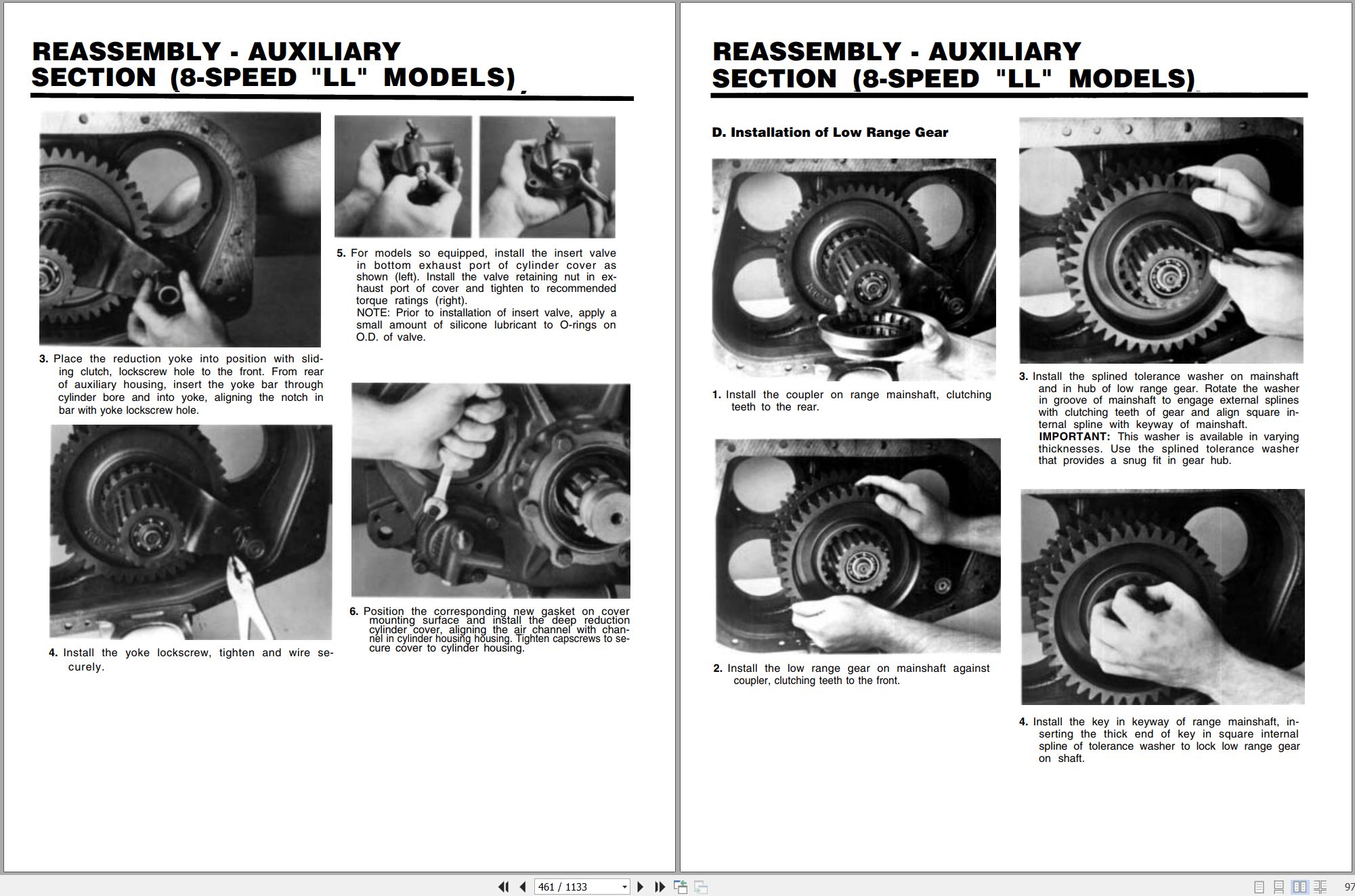
XL3100-04EPA Combined Service Manual 3101-4005 2006.pdf (1133 Pages)
Contents:
3101-4005 XL3100-04EPA COMBINED SERVICE MANUAL
OPERATOR INSTRUCTION
3101-4004 Operator/Safety Manual
HYDRAULIC TEST & ADJUSTMENT
8030-9019 Hydraulic Schematic
RDE92703-01-R Rexroth Main Pump Repair Manual
RDE 92711-02-R Rexroth Main Pump Repair A10VSO*
RDE91001-01-R Rexroth Swing Motor/Remote Drive Motor
RA64555 Rexroth Joystick
8030-9021 Start Up Procedure
MECHANICAL ADJUSTMENT
F36758 Ausco “C” Series Failsafe Brake
S6A Fairfield Torque-Hub Final Drives Service Manual
MISCELLANEOUS
8048-9008 Electrical Schematic
F114004 Donaldson Cyclopac Service Procedure
8038-9001 Chassis Electrical Schematic
STEERING
WA-TRW 1108 TRW Steering Gear Service Manual
I-3143-S Vickers Vane Pump Overhaul
CLUTCH
P.N. 340186R Valeo Clutch Service Manual
CLWP-1707-4 Eaton Spicer Angle Spring Clutches Service Manual
EXC2006-7 Service Bulletin, Clutch Adjustment Procedure
MAIN TRANSMISSION
TRSM-0430 Eaton Fuller Heavy Duty Transmissions Service Manual
FRONT AXLE
MM12 Rockwell Front Drive Steering Axles Service Manual
TP-97117 Tie Rod & Cross Tube Assembly, Inspection & Maintenance
REAR AXLE
TSA-2-113 Rockwell Drive Axle Service Manual
TSA-2-112 Rockwell Axle Shafts Service Manual
FMM#5A Meritor Single Reduction Rear Differential Carriers
MM1 Lubrication Service Manual
TP-9303 Meritor Rockwell Advanced Lube Rear Drive Axles
TP-9238 Meritor Rockwell Driver-Controlled Differential Lock
DRIVE LINE
3264-2 Spicer U-Joints & Drive Shaft Service Manual
TOL-006-95 Spicer U-Joints & Driveshaft Service Manual
EXC2006-06 Service Bulletin, Torque Specs on PTO’s
BRAKE SYSTEM
8038-9008 Air Diagram
8038-9009 Air Schematic
MM#4 Meritor Cam Brakes Service Manual
SD-08-2403 Bendix AD-1 & AD-2 Air Dryers
MM#4B Rockwell Automatic Slack Adjuster
ABA-10003 Haldex Automatic Brake Adjusters
4071 MGM Brakes
BRSM-0022 Dana Automatic Slack Adjuster
WHEEL & RIM
0009 Rim & Wheel Safety
IM-298 Webb Service Manual
MISCELLANEOUS
F114005 Donaldson Air Cleaner
20013 Gradall Safety Manual
XL3100 XL3100EPA Technical Manualual 31014009 2011.pdf (479 Pages)
Contents:
31014009_XL3100 & XL3100EPA Technical Manual_5-11
ELECTRICAL
XL3100 Electrical Circuits (Cummins Engine)
XL3100EPA Electrical Circuits (Detroit Engine)
XL3100EPA Engine Troubleshooting Guide
XL3100EPA Engine Codes
HYDRAULIC
XL3100 Hydraulic System Operation
XL3100 Pressure Setting Guide
XL3100EPA Pressure Setting Guide
XL3100 Final Test Report (80309013)
XL3100EPA Final Test Report (80309022)
Start-Up Procedure (80309021)
MECHANICAL
Remote Drive PTO Removal & Placement
Maintenance Manual
Climate Control Systems
XL3100 Air System
Product Support Bulletin – Engine Oil Pan Drain Plugs
Product Support Bulletin – A/C System Reciever Dryers
Product Support Bulletin – A/C Systems & Compressed Air
Product Support Bulletin – A/C System Moisture Contamination
Product Support Bulletin – Swing Transmission Lube Check and Refill Requirements
Transmission Service Manual (Eaton)
Hydraulic Heater Circuit & A/C Circuit Operation
Product Support Bulletin – Clutch Adjustment Procedure
SCHEMATICS
(80309004) XL3100 Hydraulic Schematic (Cummins Engine)
(80309019) XL3100EPA Hydraulic Schematic (Detroit Engine)
(80389007) XL3100 Electrical Schematic (Cummins Engine)
(80489007) XL3100EPA Electrical Schematic (Detroit Engine)
(80389008 & 80389009) XL3100EPA Air Diagram & Schematic (Detroit Engine)
XL3100 Parts Manual 31200001 2004.pdf (268 Pages)
Contents:
31200001 XL3100 EPA PARTS MANUAL
UPPERSTRUCTURE
Section 1 Introduction
Section 2 Boom Assemblies
Section 3 Cab & Related Components
Section 4 Hydraulic System Components
Section 5 Main Hydraulic Systems
Section 6 Pilot Hydraulic Systems
Section 7 Attachments
UNDERCARRIAGE
Section 1 Introduction
Section 2 Undercarriage Assembly
Section 3 Drive Line Components
Section 4 Front Axle Assembly
Section 5 Rear Axle Assembly
Section 6 Air System
Section 7 Cab & Related Components
Section 8 Steering & Component Assemblies
OPTIONS
XL3100 Parts Manual 31200005 2004.pdf (267 Pages)
Contents:
31200005 XL3100 EPA PARTS MANUAL
UPPERSTRUCTURE
Section 1 Introduction
Section 2 Boom Assemblies
Section 3 Cab & Related Components
Section 4 Hydraulic System Components
Section 5 Main Hydraulic Systems
Section 6 Pilot Hydraulic Systems
Section 7 Attachments
UNDERCARRIAGE
Section 1 Introduction
Section 2 Undercarriage Assembly
Section 3 Drive Line Components
Section 4 Front Axle Assembly
Section 5 Rear Axle Assembly
Section 6 Air System
Section 7 Cab & Related Components
Section 8 Steering & Component Assemblies
OPTIONS
XL3100 EPA Parts Manual 31200011 2004.pdf (263 Pages)
Contents:
31200011 XL3100 EPA PARTS MANUAL
UPPERSTRUCTURE
Section 1 Introduction
Section 2 Boom Assemblies
Section 3 Cab & Related Components
Section 4 Hydraulic System Components
Section 5 Main Hydraulic Systems
Section 6 Pilot Hydraulic Systems
Section 7 Attachments
UNDERCARRIAGE
Section 1 Introduction
Section 2 Undercarriage Assembly
Section 3 Drive Line Components
Section 4 Front Axle Assembly
Section 5 Rear Axle Assembly
Section 6 Air System
Section 7 Cab & Related Components
Section 8 Steering & Component Assemblies
OPTIONS
XL3100 Illustrated Parts Manual 31200058 2004.pdf (518 Pages)
XL3100 Illustrated Parts Manual 31200060 2005.pdf (520 Pages)
XL3100 EPA Illustrated Parts Manual 31200067 2005.pdf (504 Pages)
XL3100 Illustrated Parts Manual 31200082 2005.pdf (476 Pages)
XL3100 EPA Illustrated Parts Manual 31200084 2005.pdf (446 Pages)
XL3100 Illustrated Parts Manual 31200090 2005.pdf (460 Pages)
XL3100 Illustrated Parts Manual 31200093 2005.pdf (434 Pages)
XL3100 Illustrated Parts Manual 31200094 2005.pdf (442 Pages)
XL3100 Illustrated Parts Manual 31200097 2005.pdf (434 Pages)
XL3100 Illustrated Parts Manual 31200099 2005.pdf (450 Pages)
XL3100 Illustrated Parts Manual 31200105 2005.pdf (442 Pages)
XL3100 Illustrated Parts Manual 31200106 2005.pdf (446 Pages)
XL3100 Illustrated Parts Manual 31200109 2005.pdf (440 Pages)
XL3100 Illustrated Parts Manual 31200133 2005.pdf (454 Pages)
XL3100 Illustrated Parts Manual 31200136 2005.pdf (452 Pages)
XL3100 Illustrated Parts Manual 31200137 2005.pdf (460 Pages)
Contents:
Service Kits
Section 1 – Frame & Attaching Parts
Section 2 – Boom
Section 3 – Attachments
Section 4 – Engine & Attaching Parts
Section 5 – Drive Train
Section 6 – Cab Assembly
Section 7 – Controls
Section 8 – Hydraulics Circuits
Section 9 – Hydraulic Components
Section 10 – Electrical
Section 11 – Decals
Section 12 – Options
Recommended Spare Parts
Parts Number Index
XL3100 Illustrated Parts Manual 31200152 2005.pdf (440 Pages)
XL3100 Illustrated Parts Manual 31200156 2005.pdf (450 Pages)
XL3100 Illustrated Parts Manual 31200176 2005.pdf (444 Pages)
XL3100 Illustrated Parts Manual 31200177 2005.pdf (448 Pages)
XL3100 Upper Electrical Schematic 80309003 2001.pdf (4 Pages)
XL3100 Hydraulic Schematic 80309004 2001.pdf (1 Pages)
XL3100 Air Diagram 80389003 2001.pdf (1 Pages)
XL3100 Air Schematic 80389004 2001.pdf (1 Pages)
XL3100 Chassis XL3100EPA Electrical Schematic 80389007 2001.pdf (8 Pages)
XL3100 EPA Air Diagram 80389008.pdf (1 Pages)
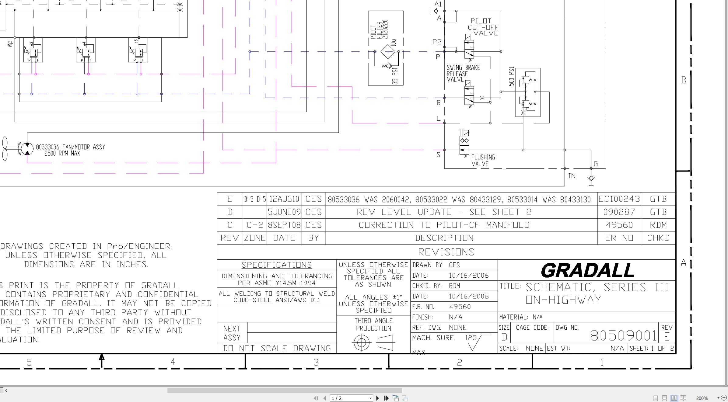
XL3100III XL3100 XL4100III XL5100III Hydraulic Schematic 80509001.pdf (2 Pages)
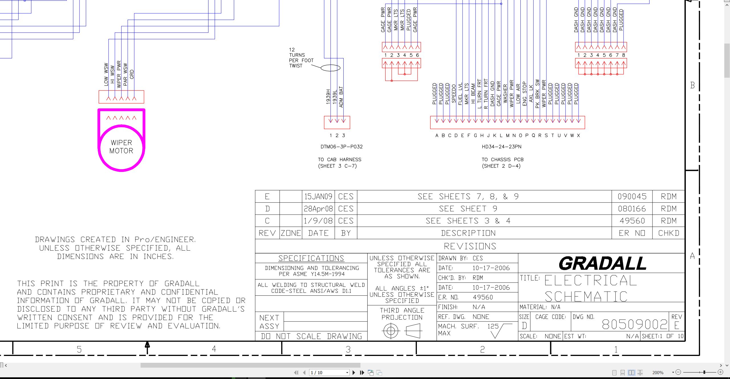
XL3100III XL3100 XL4100III XL5100III Electrical Schematic 80509002.pdf (10 Pages)
XL3100 XL3100IV XL4100 XL4100IV XL5100IV to XL5130V Railgear Hydraulic Schematic 80709006.pdf (2 Pages)
XL3100IV XL3100 to XL4100 HIGHWAY WHEELED XL4100IV XL5100IV Electrical Schematic 80709007.pdf (11 Pages)
XL4100V XL3100V XL4100V XL3100V to XL3100V XL3100 XL4100V Electrical Schematic 80709015.pdf (12 Pages)
XL4100V XL4100 XL4100V to XL3100V XL3100 XL3100V XL3100 XL3100V Electrical Schematic 80709027.pdf (15 Pages)
XL4100V XL4100 XL4100V to XL3100V XL3100 XL3100V XL3100 XL3100V Electrical Schematic 80709027.pdf (15 Pages)
Series V XL3100V XL4100V XL5100V XL3100 XL4100 XL5100 Illustrated Parts Manual 80884032 2026.pdf (778 Pages)
Contents:
80884032_D_SV Highway Speed Parts Manual_3-2026
Effectivity Page
Table of Contents
Understanding Your Manual
Section 1 – Frame & Attaching Parts
Section 2 – Boom
Section 3 – Attachments
Section 4 – Engine & Attaching Parts
Section 5 – Drive Train
Section 6 – Cab
Section 7 – Controls
Section 8 – Hydraulic Circuits
Section 9 – Hydraulic Components
Section 10 – Electrical
Section 11 – Decals
Section 12 – Options
Recommended Spare Parts
Part Number Index
Series V XL3100V XL4100V XL5100V XL3100 XL4100 XL5100 Operator Safety Manual 80884033 2026.pdf (172 Pages)
Contents:
Section 1 – General Safety Practices
1.1 Hazard Classification System
1.2 General Precautions
1.3 Operation Safety
1.4 Personal Protection Equipment
Section 2 – Pre-Operation and Controls
2.1 Pre-Operation Checks & Inspection
2.2 Walk-Around Inspection
2.3 Safety Decals
2.4 Undercarriage Cab Components
2.5 Transmission Shift Selector
2.6 Undercarriage Cab Controls & Indicators
2.7 Upperstructure Cab Components
2.8 Upperstructure Cab Controls & Indicators
Section 3 – Operation
3.1 Travel Mode Engine Operation
3.2 Checks Before Undercarriage Operation
3.3 Travel Mode Brake System
3.4 Travel Mode Power Train
3.5 Travel Mode Engine Shutdown
3.6 Remote Control Preparation
3.7 Checks Before Remote Control Operation
3.8 Remote Mode Brake System
3.9 Remote Mode Power Train
3.10 Steering System
3.11 Typical Dig Cycle
3.12 Lifting & Placing a Load
3.13 Lift Capacity
3.14 Remote Mode Engine Shutdown
3.15 Return to Travel Mode
3.16 Parking the Excavator
3.17 Preservation & Storage
3.18 Parked Regeneration (Stage V Engines)
Section 4 – Attachments
4.1 Approved Attachments
4.2 Unapproved Attachments
4.3 Attachment Operation
4.4 Adapter Attachment Installation
Section 5 – Lubrication & Maintenance
5.1 Introduction
5.2 General Maintenance Instructions
5.3 Service & Maintenance Schedules
5.4 Undercarriage Lubrication Schedules
5.5 Upperstructure Lubrication Schedules
5.6 Operator Maintenance Instructions
Section 6 – Emergency Procedures
6.1 Loss Of Power
Section 7 – Specifications
7.1 Product Specifications
7.2 Torque Chart
7.3 Fuses
Index
Series V XL3100V XL4100V XL5100V XL3100 XL4100 XL5100 Service Manual 80884034 2026.pdf (1189 Pages)
Contents:
80884034_C_Series V Highway Speed Combined Service Manual_3-2026
VOLUME I
80884033_C_Series V Highway Speed Op & Safety Manual_3-2026
HYDRAULIC TEST & ADJUSTMENT
MECHANICAL ADJUSTMENT
ELECTRICAL
STEERING
MAIN TRANSMISSION
VOLUME II
FRONT AXLE
REAR AXLE
DRIVE LINES
BRAKE SYSTEMS
MISCELLANEOUS
XL3100 Highway Wheeled XL3100III Air Diagram 80889010.pdf (1 Pages)
XL3100 XL3100III Air Schematic 80889011.pdf (1 Pages)
XL3100 XL3100IV Air Schematic 80889016.pdf (1 Pages)
XL3100 XL3100V Air Schematic 80889029.pdf (1 Pages)
XL3100 Highway Wheeled XL3100V Air Diagram 80889030.pdf (1 Pages)
XL3100 XL3100V Air Schematic 80889039.pdf (1 Pages)
SIII Highway Speed Vendor Component XL3100 XL3100III to XL5100III Service Manual CLSM0100 2006.pdf (969 Pages)
Related Products
-
Gradall Wheeled Excavator XL4300IICE Operators Service Manual 31200155 2006
30 USDSize: 130.81 MBFormat: PDFLanguage: EnglishBrand: GradallType of Machine: Rough-terrain Wheeled ExcavatorType of Manual: Combined Service Manual, Operators Manual, Hydraulic Schematic, Electrical SchematicModel: Gradall XL4300IICE 31200155, XL4300IICE 31200154 Rough-terrain Wheeled ExcavatorSerial Number: 0210017803Part Number: XL4300IICE 31200155, XL4300IICE 31200154Publication Date: 31200155 – 2006, 31200154 – 2005Number of Pages: 953 Pages
REALEASE :
REALEASE :
-
Gradall Wheeled Excavator XL3300V Operators Parts Service Manual
30 USDSize: 214.38 MBFormat: PDFLanguage: EnglishBrand: GradallType of Machine: Rough-terrain Wheeled ExcavatorType of Manual: Electrical Schematic, Hydraulic Schematic, Illustrated Parts Manual, Lubrication Chart, Operator Safety Manual, Parts Manual, Service SupplementModel: Gradall XL3300V Rough-terrain Wheeled Excavator
REALEASE :
REALEASE :
-
Gradall Wheeled Excavator XL5300V Operators Parts Service Manual
30 USDSize: 214.38 MBFormat: PDFLanguage: EnglishBrand: GradallType of Machine: Rough-terrain Wheeled ExcavatorType of Manual: Electrical Schematic, Hydraulic Schematic, Illustrated Parts Manual, Lubrication Chart, Operator Manual, Safety Manual, Parts Manual, Service SupplementModel: Gradall XL5300V Rough-terrain Wheeled Excavator
REALEASE :
REALEASE :
-
Gradall Wheeled Excavator XL4300V Operators Parts Service Manual
30 USDSize: 252.03 MBFormat: PDFLanguage: EnglishBrand: GradallType of Machine: Rough-terrain Wheeled ExcavatorType of Manual: Assembly Manual, Electrical Schematic, Hydraulic Schematic, Illustrated Parts Manual, Installation Instructions, Installation Parts Manual, Lubrication Chart, Maintenance Manual, Operator Manual, Safety Manual, Operators Instruction, Parts Manual, Service Supplement, User ManualModel: Gradall XL4300V Rough-terrain Wheeled Excavator
REALEASE :
REALEASE :
-
Gradall Wheeled Excavator XL5300III Operators Parts Service Manual
30 USDSize: 311.43 MBFormat: PDFLanguage: EnglishBrand: GradallType of Machine: Rough-terrain Wheeled ExcavatorType of Manual: Electrical Schematic, Hydraulic Schematic, Illustrated Parts Manual, Lubrication Chart, Operator Manual, Safety Manual, Parts Manual, Service Manual, Service SupplementModel: Gradall XL5300III Rough-terrain Wheeled Excavator
REALEASE :
REALEASE :
-
Gradall Wheeled Excavator XL4300II Operators Parts Service Technical Manual
30 USDSize: 355.36 MBFormat: PDFLanguage: EnglishBrand: GradallType of Machine: Rough-terrain Wheeled ExcavatorType of Manual: Combined Service Manual, Electrical Schematic, Hydraulic Schematic, Illustrated Parts Manual, Operators Manual, Parts Manual, Service Manual, Technical ManualModel: Gradall XL4300II Rough-terrain Wheeled Excavator
REALEASE :
REALEASE :
-
Gradall Wheeled Excavator XL5300 Operators Parts Service Manual
30 USDSize: 309.61 MBFormat: PDFLanguage: EnglishBrand: GradallType of Machine: Rough-terrain Wheeled ExcavatorType of Manual: Electrical Schematic, Hydraulic Schematic, Illustrated Parts Manual, Operator Manual, Safety Manual, Parts Manual, Service Manual, Service SupplementModel: Gradall XL5300 Rough-terrain Wheeled Excavator
REALEASE :
REALEASE :
-
Gradall Wheeled Excavator XL4300 Operators Parts Service Manual
30 USDSize: 321.70 MBFormat: PDFLanguage: EnglishBrand: GradallType of Machine: Rough-terrain Wheeled ExcavatorType of Manual: Electrical Schematic, Hydraulic Schematic, Illustrated Parts Manual, Lubrication Chart, Operator Manual, Safety Manual, Parts Manual, Service Manual, Service SupplementModel: Gradall XL4300 Rough-terrain Wheeled Excavator
REALEASE :
REALEASE :