
41 ITEMSVIEW CART


Total: 3,207.20
Expert Support
Full Speed
100% Working
30 USD
List of Files:
XL3200 Illustrated Parts Manual 31200225 2006.pdf (232 Pages)
Contents:
Service Kits
Section 1 Frame & Attaching Parts
Figure 1-1 Frame Assembly
Figure 1-2 Rotating Platform
Figure 1-3 Swing Bearing, Cradle & Hoist Cylinder Mounting & Lube System
Figure 1-4 Valve Cover
Figure 1-5 Engine Cover
Section 2 Boom
Figure 2-1 Boom Cradle
Figure 2-2 Main Boom Assembly & Roller Assemblies
Figure 2-3 Telescope Boom Assembly
Figure 2-4 Roller Assemblies
Figure 2-5 Bucket Linkage
Figure 2-6 Boom Hood and Stabilizer Mounting
Section 3 Attachments
Figure 3-1 60†Ditching Buckets
Section 4 Engine & Attaching Parts
Figure 4-1 Engine Assembly
Figure 4-2 John Deere Engine
Figure 4-3 Air Cleaner & Installation
Figure 4-4 Air Cleaner Assembly
Figure 4-5 Exhaust System
Figure 4-6 Fuel Tank Assembly
Figure 4-7 Oil Cooler, Radiator & Hoses
Section 5 Drive Train
Figure 5-1 Track Chain & Shoes
Figure 5-2 Track Roller
Figure 5-3 Carrier Roller
Figure 5-4 Front Idler Track Adjuster
Figure 5-5 Crawler Drive – Control
Figure 5-6 Crawler Drive – Hydraulic Motor
Figure 5-7 Crawler Drive – Gearbox
Section 6 Cab
Figure 6-1 Operators Cab
Figure 6-2 Operators Cab
Figure 6-3 Cab Door
Figure 6-4 Cab Interior Components
Figure 6-5 Cab Console
Figure 6-6 Cab Seat
Figure 6-7 Cab Heater & Installation
Section 7 Controls
Figure 7-1 Joystick Assembly
Figure 7-2 Foot Pedals & Installation
Section 8 Hydraulic Circuits
Figure 8-1 Oil Supply to Pumps
Figure 8-2 Hydraulic Pressure to Control Valves
Figure 8-3 Main Valve to Pilot Manifold Hydraulic Hosing
Figure 8-4 Hydraulic Hosing to Joysticks & Foot Operated Valves
Figure 8-5 Dump Circuit
Figure 8-6 Hoist Pilot
Figure 8-7 Boom Pilot
Figure 8-8 Tool Pilot
Figure 8-9 Swing & Swing Brake Pilot
Figure 8-10 Tilt & Auxiliary Pilot
Figure 8-11 Hoist Cylinder Hydraulic Circuit
Figure 8-12 Boom Cylinder Hydraulic Circuit
Figure 8-13 Tool Cylinder Hydraulic Circuit
Figure 8-14 Swing Motor
Figure 8-15 Tilt Motor
Figure 8-16 Upper Propelling
Figure 8-17 Drive Main
Figure 8-18 Drive Forward/Reverse
Figure 8-19 Auxiliary Hydraulic Circuit
Section 9 Hydraulic Components
Figure 9-1 Hoist Cylinder Assembly
Figure 9-2 Boom Cylinder
Figure 9-3 Tool Cylinder Assembly
Figure 9-4 Main Pump – Front
Figure 9-5 Main Pump – Rear
Figure 9-6 Pilot Manifold Valve Tray Hydraulic Components
Figure 9-7 Pilot Manifold
Figure 9-8 Main Hydraulic Control Valve
Figure 9-9 Main Hydraulic Control Valve – Spools & End Caps
Figure 9-10 Main Hydraulic Control Valve – Swing Section
Figure 9-11 Main Hydraulic Control Valve – Seal Kits
Figure 9-12 Reservoir Assembly
Figure 9-13 Swing Transmission Installation
Figure 9-14 Swing Transmission
Figure 9-15 Swing Motor
Figure 9-16 Swing Brake
Figure 9-17 Tilt Transmission
Figure 9-18 Tilt Transmission Assembly
Figure 9-19 Tilt Brake
Figure 9-20 Tilt Motor
Figure 9-21 Center Pin
Figure 9-22 Foot Operated Pedal Valve
Figure 9-23 Thermal By-Pass Valve
Section 10 Electrical
Figure 10-1 Batteries & Miscellaneous Electrical Components
Figure 10-2 Printed Circuit Board
Section 11 Decals
Figure 11-1 Decals
Section 12 Options
Figure 12-1 Air Conditioner Kit Installation Components
Figure 12-2 Air Conditioner Evaporator Kit Installation Components
Figure 12-3 AM/FM Radio & Antenna Installation Components
Figure 12-4 Floodlight Installation Components
Recommended Spare Parts
Part Number Index
XL3200 Illustrated Parts Manual 31200283 2007.pdf (234 Pages)
Contents:
Service Kits
Section 1 Frame & Attaching Parts
Figure 1-1 Frame Assembly
Figure 1-2 Rotating Platform
Figure 1-3 Swing Bearing, Cradle & Hoist Cylinder Mounting & Lube System
Figure 1-4 Valve Cover
Figure 1-5 Engine Cover
Figure 1-6 Cab Covers and Lift Points
Section 2 Boom
Figure 2-1 Boom Cradle
Figure 2-2 Main Boom Assembly
Figure 2-3 Telescope Boom Assembly
Figure 2-4 Roller Assemblies
Figure 2-5 Bucket Linkage
Figure 2-6 Boom Hood and Stabilizer Mounting
Section 3 Attachments
Figure 3-1 30†Excavating Bucket
Figure 3-2 Double Tooth Ripper Installation
Figure 3-3 Lower Ripper Weld
Figure 3-4 Upper Ripper Weld
Figure 3-5 Hammer Installation
Section 4 Engine & Attaching Parts
Figure 4-1 Engine Assembly
Figure 4-2 John Deere Engine
Figure 4-3 Air Cleaner & Installation
Figure 4-4 Air Cleaner Assembly
Figure 4-5 Exhaust System
Figure 4-6 Fuel Tank Assembly
Figure 4-7 Oil Cooler, Radiator & Hoses
Section 5 Drive Train
Figure 5-1 Track Chain & Shoes
Figure 5-2 Track Roller
Figure 5-3 Carrier Roller
Figure 5-4 Front Idler Track Adjuster
Figure 5-5 Crawler Drive – Control
Figure 5-6 Crawler Drive – Hydraulic Motor
Figure 5-7 Crawler Drive – Gearbox
Section 6 Cab
Figure 6-1 Operators Cab
Figure 6-2 Cab Door
Figure 6-3 Cab Interior Components
Figure 6-4 Cab Console
Figure 6-5 Cab Seat, Upperstructure
Figure 6-6 Cab Heater & Installation
Figure 6-7 Pilot Cut-off Assembly
Section 7 Controls
Figure 7-1 Joystick Assembly
Figure 7-2 Foot Pedals & Installation
Section 8 Hydraulic Circuits
Figure 8-1 Oil Supply to Pumps
Figure 8-2 Hydraulic Pressure to Control Valves
Figure 8-3 Main Valve to Pilot Manifold Hydraulic Hosing
Figure 8-4 Hydraulic Hosing to Joysticks & Foot Operated Valves
Figure 8-5 Dump Circuit
Figure 8-6 Hoist Pilot
Figure 8-7 Boom Pilot
Figure 8-8 Tool Pilot
Figure 8-9 Swing & Swing Brake Pilot
Figure 8-10 Tilt & Auxiliary
Figure 8-11 Hoist Cylinder
Figure 8-12 Boom Cylinder Hydraulic Circuit
Figure 8-13 Tool Cylinder
Figure 8-14 Auxiliary Hydraulic Circuit
Figure 8-15 Swing Motor
Figure 8-16 Tilt Motor
Figure 8-17 Upper Propelling
Figure 8-18 Drive Main
Figure 8-19 Drive Forward/Reverse
Section 9 Hydraulic Components
Figure 9-1 Hoist Cylinder Assembly
Figure 9-2 Boom Cylinder
Figure 9-3 Tool Cylinder Assembly
Figure 9-4 Main Pump – Front
Figure 9-5 Main Pump – Rear
Figure 9-6 Pilot Manifold Valve Tray Hydraulic Components
Figure 9-7 Pilot Manifold
Figure 9-8 Main Hydraulic Control Valve
Figure 9-9 Main Hydraulic Control Valve – Spools & End Caps
Figure 9-10 Main Hydraulic Control Valve – Swing Section
Figure 9-11 Main Hydraulic Control Valve – Seal Kits
Figure 9-12 Reservoir Assembly
Figure 9-13 Swing Transmission Installation
Figure 9-14 Swing Transmission
Figure 9-15 Swing Motor
Figure 9-16 Swing Brake
Figure 9-17 Tilt Transmission
Figure 9-18 Tilt Transmission Assembly
Figure 9-19 Tilt Brake
Figure 9-20 Tilt Motor
Figure 9-21 Center Pin
Figure 9-22 Foot Operated Pedal Valve
Figure 9-23 Thermal By-Pass Valve
Section 10 Electrical
Figure 10-1 Batteries & Miscellaneous Electrical Components
Figure 10-2 Printed Circuit Board
Section 11 Decals
Figure 11-1 Decals
Section 12 Options
Figure 12-1 Floodlight Installation Components
Recommended Spare Parts
Part Number Index
XL3200 Combined Service Manual 3200-4002 2004.pdf (400 Pages)
Contents:
3200-4002 XL3200 COMBINED SERVICE MANUAL
OPERATOR INSTRUCTION
29907 XL3200 Owner/Operator Manual
SCHEDULED MAINTENANCE
N/A 20003 XL3200 Scheduled Maintenance Manual
20004 J Deere Liquid Coolant Test Manual
HYDRAULIC SYSTEM OPERATION
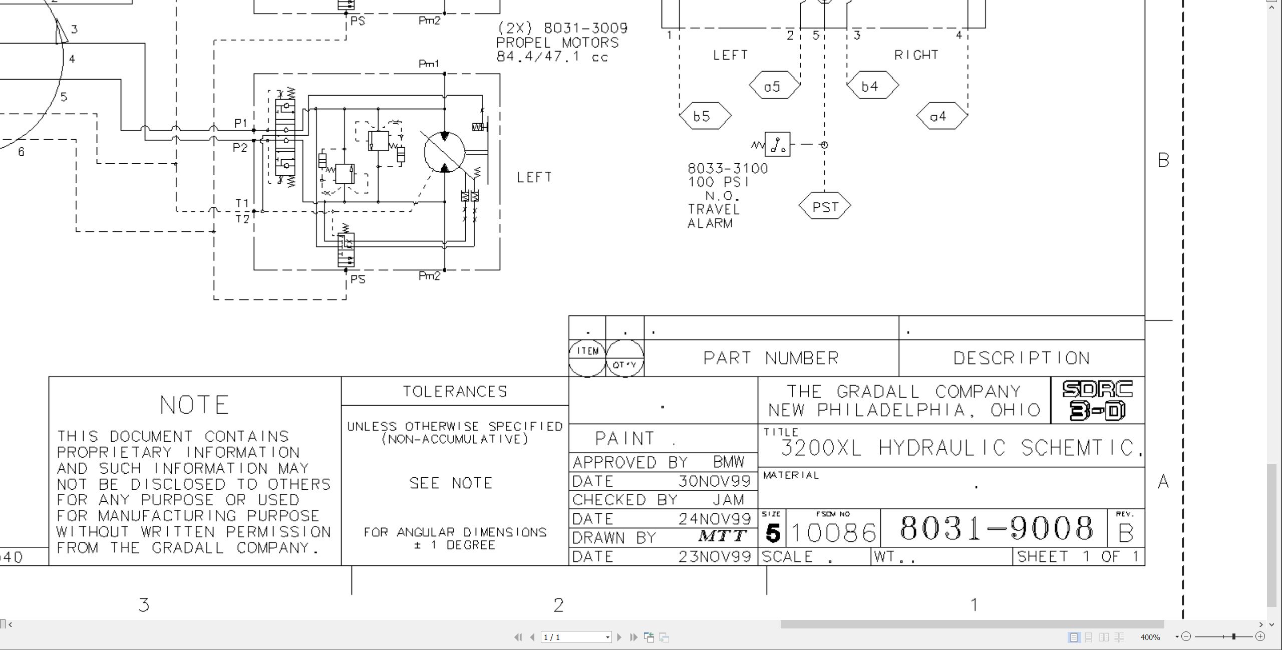
8031-9008 Hydraulic Schematic
8031-9004 Start-Up Procedure
RA64555 Rexroth Joystick Installation
MECHANICAL ADJUSTMENT
SM1512-002 Parker Hydraulic Motors Service Manual
75580 Ausco Brake Technical Page
29712 Boom Extension Installation
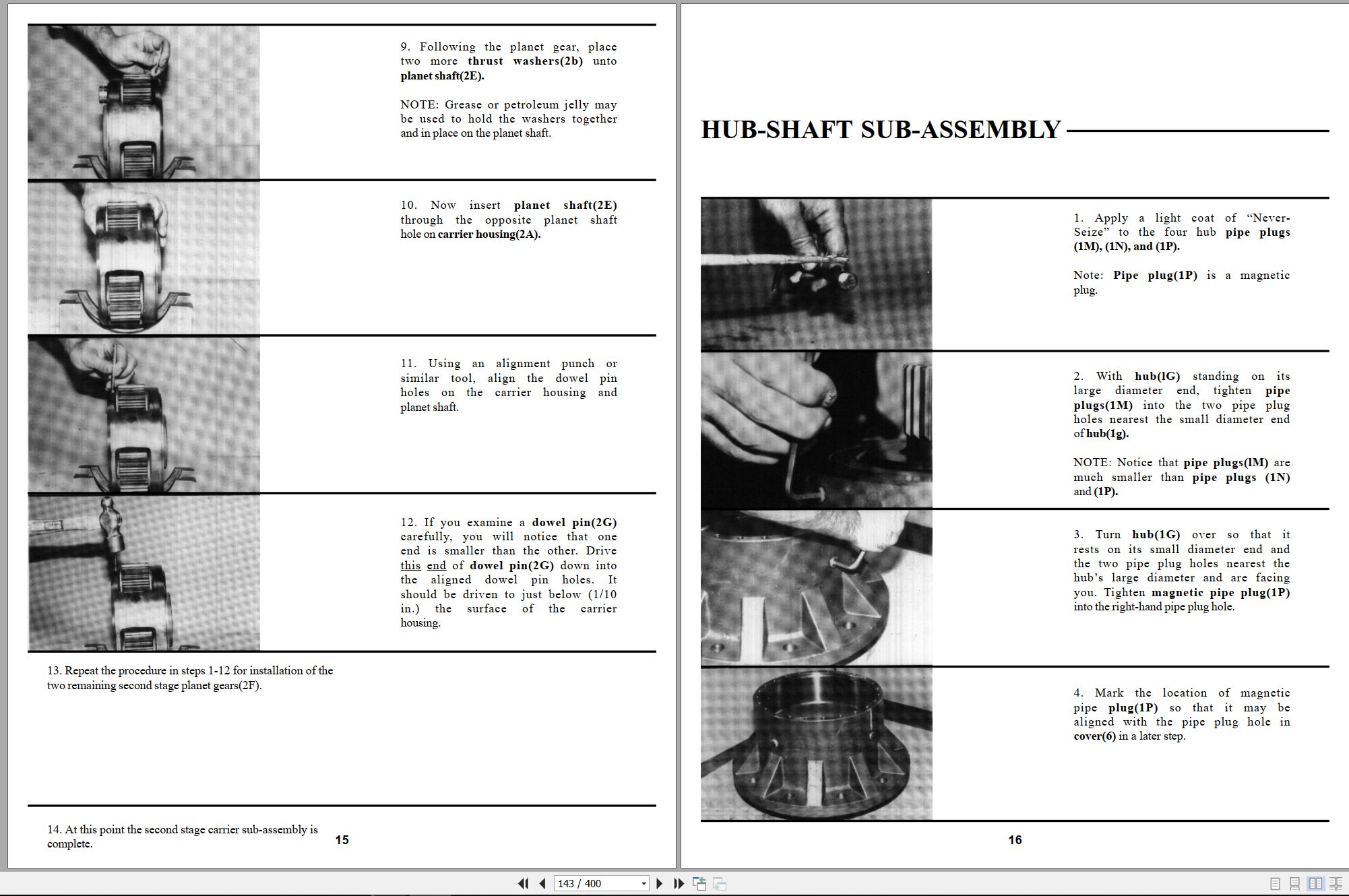
S6A Fairfield Torque-Hub Service Manual
ELECTRICAL
1M-128 Delco Remy Cranking Motor Service Manual
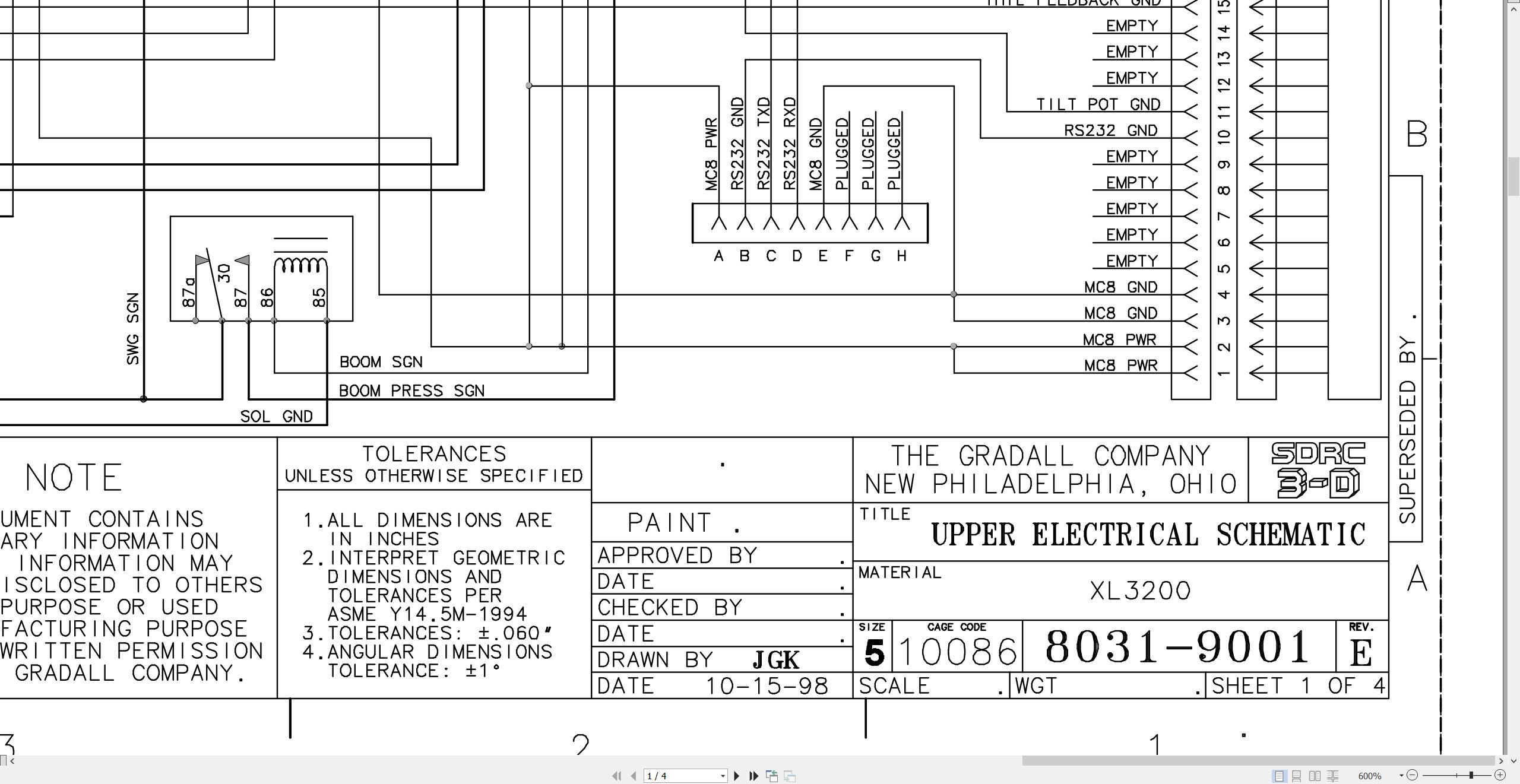
8031-9001 Upper Electrical Schematic
8036-3016 Upper Harness
8036-3025 Engine Harness
8036-3026 Cab Harness
8036-5003 Console Assembly Wiring Diagram
CRAWLER
29635 XL Series Crawler Maintenance Manual
29302 Kayaba Service Manual
MISCELLANEOUS
HE92-2 EMI Safety Manual.pdf
20013 Gradall Safety Manual
XL3200 Operators Manual 3200-4003 2004.pdf (52 Pages)
Important Safety Notices
List Of Effective Pages
Table Of Contents
Introduction
General
Related Manuals & Decals
Operator Qualifications
Orientation
Pin Plate Location
Models Covered
Nomenclature
Nomenclature
Tool Kit
Safety Highlights
Decals
Decals Inside Cab
Decals Outside Cab
Serial No. Plates
Operator’s Cab
Seat Adjustment
Heater
Air Conditioner
Defrost
Ventilation
Wiper/Washer
12 Vdc Accessory Outlets
Control & Instrument Identification
Electronic Monitor
Checks & Services Before Starting Engine
Engine Operation
Starting John Deere Engine
Cold Weather Starting Aids
Normal Engine Operations
Auto Idle (Fuel Saving)
Stopping The Engine
Warm Up & Operational Checks
Adapter Attachment Installation
Use Your Crawler Properly
Crawler Controls
How To Operate The Crawler
Lifting & Positioning A Load
Precautions
General
Positioning Machine For A Lift
Planning A Lift
Recommended Lubricants & Capacities
Torque Chart
Lubrication & Maintenance Diagram
Securing Boom
Emergency Towing
If You Get Stuck
Loading And Securing Machine For Transport
Preservation & Storage
Excavator Hand Signals
XL3200 Illustrated Parts Manual 32004001 2024.pdf (324 Pages)
Contents:
Section 1 Frame & Attaching Parts
Figure 1-1 Frame Assembly
Figure 1-2 Upperstructure Mirror Installation
Figure 1-3 Upperstructure Mirror Installation (service only)
Figure 1-4 Upperstructure Covers Installation
Figure 1-5 Swing Bearing, Cradle & Hoist Cylinder Mounting & Lube System
Figure 1-6 Valve Cover
Figure 1-7 Engine Cover
Figure 1-8 Counterweight & Swing Light Installation
Figure 1-9 Cab Installation Components
Section 2 Boom
Figure 2-1 Boom Cradle
Figure 2-2 Main Boom Assembly
Figure 2-3 Telescope Boom Assembly
Figure 2-4 Boom Roller Assemblies
Figure 2-5 Bucket Linkage
Section 3 Attachments
Figure 3-1 24†& 30†Excavating Buckets
Figure 3-2 36†Excavating Bucket & 30†Pavement Removal Bucket
Figure 3-3 48†& 60†Ditching Buckets
Figure 3-4 60†& 66†Ditching Buckets
Figure 3-5 Single Tooth Ripper & 8’ Grading Blade
Figure 3-6 4’ Boom Extension
Figure 3-7 Fixed Thumb Grapple
Figure 3-8 Limb Lopper
Figure 3-9 Telestick Installation
Figure 3-10 Telestick Installation w/Quick Attach
Section 4 Engine & Attaching Parts
Figure 4-1 Engine Assembly
Figure 4-2 John Deere Engine
Figure 4-3 Flywheel Coupler Assembly
Figure 4-4 Air Cleaner & Installation
Figure 4-5 Air Cleaner Assembly
Figure 4-6 Fuel Tank Assembly
Figure 4-7 Oil Cooler, Radiator & Hoses
Section 5 Drive Train
Figure 5-1 Track Chain & Shoes
Figure 5-2 Track Roller
Figure 5-3 Carrier Roller
Figure 5-4 Front Idler Track Adjuster
Figure 5-5 Crawler Drive – Control
Figure 5-6 Crawler Drive – Hydraulic Motor
Figure 5-7 Crawler Drive – Gearbox
Section 6 Cab
Figure 6-1 Operators Cab Assembly
Figure 6-2 Operators Cab
Figure 6-3 Operators Cab Door
Figure 6-4 Operators Cab Console
Figure 6-5 Operators Cab Seat
Figure 6-6 Heater Assembly
Figure 6-7 Pilot Cut-off Assembly
Section 7 Controls
Figure 7-1 Joystick Assembly
Figure 7-2 Foot Pedal Plate Assembly
Section 8 Hydraulic Circuits
Figure 8-1 Oil Supply to Pumps
Figure 8-2 Hydraulic Pressure to Control Valves
Figure 8-3 Main Valve to Pilot Manifold Hydraulic Hosing
Figure 8-4 Hydraulic Hosing to Joysticks & Foot Operated Valves
Figure 8-5 Dump Circuit
Figure 8-6 Hoist Pilot
Figure 8-7 Boom Pilot
Figure 8-8 Tool Pilot
Figure 8-9 Swing & Swing Brake Pilot
Figure 8-10 Tilt & Auxiliary
Figure 8-11 Hoist Cylinder
Figure 8-12 Boom Cylinder
Figure 8-13 Tool Cylinder
Figure 8-14 Swing Motor
Figure 8-15 Tilt Motor
Figure 8-16 Upper Propelling
Figure 8-17 Drive Main
Figure 8-18 Drive Forward/Reverse
Section 9 Hydraulic Components
Figure 9-1 Hoist Cylinder Assembly
Figure 9-2 Boom Cylinder Assembly
Figure 9-3 Tool Cylinder Assembly
Figure 9-4 Main Pump – Front
Figure 9-5 Main Pump – Rear
Figure 9-6 Pilot Manifold Valve Tray Hydraulic Components
Figure 9-7 Pilot Manifold
Figure 9-8 Main Hydraulic Control Valve Assembly
Figure 9-9 Main Hydraulic Control Valve
Figure 9-10 Main Hydraulic Control Valve – Spools & End Caps
Figure 9-11 Main Hydraulic Control Valve – Swing Section
Figure 9-12 Main Hydraulic Control Valve – Seal Kits
Figure 9-13 Reservoir Assembly
Figure 9-14 Swing Transmission Assembly
Figure 9-15 Swing Drive Assembly
Figure 9-16 Swing Motor Assembly
Figure 9-17 Swing Brake
Figure 9-18 Tilt Transmission Assembly
Figure 9-19 Tilt Drive Assembly
Figure 9-20 Tilt Brake Assembly
Figure 9-21 Tilt Motor Assembly
Figure 9-22 Center Pin
Figure 9-23 Foot Operated Pedal Valve
Figure 9-24 Thermal By-Pass Valve
Section 10 Electrical
Figure 10-1 Batteries & Miscellaneous Electrical Components
Figure 10-2 Printed Circuit Board
Section 11 Decals
Figure 11-1 Decals
Section 12 Options
Figure 12-1 Air Conditioning Installation
Figure 12-2 Air Conditioning Evaporator Kit
Figure 12-3 AM/FM Radio Installation
Figure 12-4 AM/FM Radio Installation
Figure 12-5 Auxiliary Hydraulics Field Installation
Figure 12-6 Additional Battery Installation
Figure 12-7 Cold Start Installation
Figure 12-8 Engine Block Heater Installation
Figure 12-9 Fire Extinguisher Installation
Figure 12-10 Floodlight Installation
Figure 12-11 HID Floodlight Installation
Figure 12-12 Seat Belt Installation Components
Figure 12-13 Wiper/Washer Installation
Recommended Spare Parts
Part Number Index
XL3200 XL3300 Technical Manual 32004004 2011.pdf (656 Pages)
Contents:
32004004_XL3200 & XL 3300 Technical Manual_5-11
ELECTRICAL
XL3200 Electrical System Manual
XL3300 Electrical System Manual
BB-3 Control Panel
HYDRAULIC
XL3200 Hydraulic System Manual
XL3300 Hydraulic System Manual
XL3200 & XL3300 Hydraulic System Operation Supplement
XL3200 Pressure Setting Guide (Troubleshooting)
XL3300 Pressure Setting Manual
XL3200 Final Test Report
XL3300 Final Test Report
MECHANICAL
Rough Terrain Excavator Maintenance Manual (XL3300)
Crawler Excavator Maintenance Manual (XL3200)
XL3300 Transmission Service Manual
XL3300 Axle Service Manual
XL3300 Torque Specs (80319006)
Hydraulic Fitting Torque Chart (80609016)
Loctite Chart (80319007)
Product Support Information – Swing Transmission Lube Check & Refill
Product Support Information – A/C System Reciever Dryers
Product Support Information – A/C System Moisture Contamination
Product Support Information – A/C Systems & Compressed Air
SCHEMATICS
XL3300 Hydraulic Schematic (80339005)
XL3300 Upper Electrical Schematic (80339006)
XL3200 Hydraulic Schematic (80319008)
XL3200 Upper Electrical Schematic (80319001)
XL3200 XL3210 Upper Electrical Schematic 80319001.pdf (4 Pages)
XL3200 XL3210 Hydraulic Schematic 80319008 2000.pdf (1 Pages)
XL3200 XL3200III XL4200 XL4200III XL5200 XL5200III Hydraulic Schematic 80719001.pdf (1 Pages)
XL3200 XL3200III XL4200 XL4200III XL5200 XL5200III Electrical Schematic 80719002.pdf (6 Pages)
XL3200V XL3200 XL3200 to XL5210 XL5210V XL5210 XL5210V Electrical Schematic 80719020.pdf (8 Pages)
XL3200V XL3200V XL3200V to XL5210V XL5210V XL5210V Hydraulic Schematic 80719022.pdf (1 Pages)
XL3200III XL4200III XL5200III XL3210III XL4210III to XL3220III Illustrated Parts Manual 80744001 2026.pdf (656 Pages)
Contents:
Section 1 – Frame & Attaching Parts
Section 2 – Boom
Section 3 – Attachments
Section 4 – Engine & Attaching Parts
Section 5 – Drive Train
Section 6 – Cab
Section 7 – Controls
Section 8 – Hydraulic Circuits
Section 9 – Hydraulic Components
Section 10 – Electrical
Section 11 – Decals
Section 12 – Options
Recommended Spare Parts
Part Number Index
XL3200III XL4200III XL5200III XL3210III XL5210III to XL3220III Operator Safety Manual 80744002 2024.pdf (116 Pages)
Contents:
Section 1 – General Safety Practices
1.1 Hazard Classification System
1.2 General Precautions
1.3 Operation Safety
1.4 Personal Protection Equipment
Section 2 – Pre-Operation and Controls
2.1 Pre-Operation Checks & Inspection
2.2 Walk-Around Inspection
2.3 Safety Decals – XL3200III, XL4200III & XL5200III
2.4 Safety Decals – XL3200III, XL4200III & XL5200III (CE)
2.5 Safety Decals – XL3210III, XL4210III & XL5210III
2.6 Safety Decals – XL3210III, XL4210III & XL5210III (CE)
2.7 Cab Components
2.8 Cab Controls & Indicators
Section 3 – Operation
3.1 Engine Operation
3.2 Checks Before Operation
3.3 Crawler Chassis
3.4 Typical Dig Cycle
3.5 Lifting & Placing a Load – XL3200III, XL4200III & XL5200III
3.6 Lift Capacity – XL3200III, XL4200III & XL5200III
3.7 Engine Shutdown
3.8 Parking the Excavator
3.9 Preservation & Storage
Section 4 – Attachments
4.1 Approved Attachments
4.2 Unapproved Attachments
4.3 Attachment Operation
4.4 Adapter Attachment Installation
Section 5 – Lubrication & Maintenance
5.1 Introduction
5.2 General Maintenance Instructions
5.3 Service & Maintenance Schedules
5.4 Lubrication Schedules
Section 6 – Emergency Procedures
6.1 Loss Of Power
6.2 If You Get Stuck
Section 7 – Specifications
7.1 Product Specifications
7.2 Torque Chart
7.3 Fuses
Pre-Operation Inspection Checklist
Index
XL3200V XL4200V XL5200V to XL5210V XL3200V Low-Profile Illustrated Parts Manual 80744006 2025.pdf (640 Pages)
Contents:
Section 1 – Frame & Attaching Parts
Section 2 – Boom
Section 3 – Attachments
Section 4 – Engine & Attaching Parts
Section 5 – Drive Train
Section 6 – Cab
Section 7 – Controls
Section 8 – Hydraulic Circuits
Section 9 – Hydraulic Components
Section 10 – Electrical
Section 11 – Decals
Section 12 – Options
Recommended Spare Parts
Part Number Index
XL3200V XL4200V XL5200V XL3210V to XL3200V Low-Profile Operator Safety Manual 80744007 2026.pdf (134 Pages)
Contents:
Section 1 – General Safety Practices
1.1 Hazard Classification System
1.2 General Precautions
1.3 Operation Safety
1.4 Personal Protection Equipment
Section 2 – Pre-Operation and Controls
2.1 Pre-Operation Checks & Inspection
2.2 Walk-Around Inspection
2.3 Safety Decals – XL3200V, XL4200V & XL5200V
2.4 Safety Decals – XL3210V, XL4210V & XL5210V
2.5 Cab Components
2.6 Cab Controls & Indicators
2.7 Radio Control Electrical Panel (No Cab; optional)
2.8 Radio Control Strobe Lights
Section 3 – Operation
3.1 Engine Operation
3.2 Checks Before Operation
3.3 Crawler Chassis
3.4 Typical Dig Cycle
3.5 Lifting & Placing a Load – XL3200V, XL4200V & XL5200V
3.6 Lift Capacity – XL3200V, XL4200V & XL5200V
3.7 Engine Shutdown
3.8 Parking the Excavator
3.9 Preservation & Storage
3.10 Radio Control Activation (optional)
3.11 Parked Regeneration (Stage V Engines)
Section 4 – Attachments
4.1 Approved Attachments
4.2 Unapproved Attachments
4.3 Attachment Operation
4.4 Adapter Attachment Installation
Section 5 – Lubrication & Maintenance
5.1 Introduction
5.2 General Maintenance Instructions
5.3 Service & Maintenance Schedules
5.4 Lubrication Schedules
5.5 Boom Adjustments & Maintenance
Section 6 – Emergency Procedures
6.1 Loss Of Power
6.2 If You Get Stuck
Section 7 – Specifications
7.1 Product Specifications
7.2 Torque Chart
7.3 Fuses
Pre-Operation Inspection Checklist
Index
XL3200V XL4200V XL5200V XL3210V to XL3200V Low-Profile Service Supplement 80744008 2026.pdf (250 Pages)
Contents:
Section 1 – General Safety Practices
Section 2 – Pre-Operation and Controls
Section 3 – Operation
Section 4 – Attachments
Section 5 – Lubrication & Maintenance
Section 6 – Emergency Procedures
Section 7 – Specifications
Pre-Operation Inspection Checklist
Index
ELECTRICAL
41200184_D_Bodas System Training_3-5-2026.pdf
80719020 (E) Electrical Schematic
80763138 (A) Console Circuit Board
80763158 (H) Upper Harness
80763156 (B) Cab Harness
HYDRAULIC
80719022 (-) Hydraulic Schematic
CRAWLER
XL-Series Crawler Maintenance Manual
Introduction
Nomenclature
Track Adjustment
Shoe Contact with Rock Guard
Crawler Travel Speed
Crawler Tracking
Track Chain
Track Rollers
Idler Roller with Track Tension and Adjuster Components
Driver Sprocket
Miscellaneous
SIII Crawler Mount Vendor XL3200 XL3200III to XL4210 XL5200 XL5200III XL5210 Service Literature 2010.pdf (188 Pages)

REALEASE :
REALEASE :

REALEASE :
REALEASE :

REALEASE :
REALEASE :

REALEASE :
REALEASE :

REALEASE :
REALEASE :

REALEASE :
REALEASE :

REALEASE :
REALEASE :

REALEASE :
REALEASE :
 Automotive - Heavy Equipment - Truck & Bus - Forklift - Crane