
0 ITEMSVIEW CART

✓
Expert Support
✓
Full Speed
✓
100% Working
Gradall Excavator XL3200HP Operators Parts Service Manual
Size: 78.47 MB
Format: PDF
Language: English
Brand: Gradall
Type of Machine: Crawler Telescopic Excavator
Type of Manual: Combined Service Manual, Illustrated Parts Manual, Operator Manual, Owner Manual, Parts Manual, Service Manual, Electrical Schematic, Hydraulic Schematic
Model: Gradall XL3200HP Crawler Telescopic Excavator
30 USD
- Description
Description
List of Files:
XL3200HP Illustrated Parts Manual 31200108 2006.pdf (260 Pages)
Contents:
Effectivity Page
Service Kits
Section 1 Frame & Attaching Parts
Figure 1-1 Frame Assembly
Figure 1-2 Rotating Platform
Figure 1-3 Rotating Platform
Figure 1-4 Swing Bearing, Cradle & Hoist Cylinder Mounting & Lube System
Section 2 Boom
Figure 2-1 Boom Cradle
Figure 2-2 Main Boom Assembly & Roller Assemblies
Figure 2-3 Telescope Boom Assembly
Figure 2-4 Roller Assemblies
Figure 2-5 Bucket Linkage
Section 3 Attachments
Figure 3-1 36†Excavating Bucket
Figure 3-2 60†Ditching Bucket
Figure 3-3 4’ Boom Extension
Figure 3-4 Fixed Thumb Grapple
Figure 3-5 Limb Lopper Assembly
Figure 3-6 60†Ditching Bucket for Telestick
Figure 3-7 Telestick Installation
Section 4 Engine & Attaching Parts
Figure 4-1 Engine Assembly
Figure 4-2 John Deere Engine
Figure 4-3 Air Cleaner & Installation
Figure 4-4 Air Cleaner Assembly
Figure 4-5 Exhaust System
Figure 4-6 Fuel Tank Assembly
Figure 4-7 Oil Cooler, Radiator & Hoses
Figure 4-8 Pump Coupler Assembly
Section 5 Drive Train
Figure 5-1 Track Chain & Shoes
Figure 5-2 Track Roller
Figure 5-3 Carrier Roller
Figure 5-4 Front Idler Track Adjuster
Figure 5-5 Crawler Drive – Control
Figure 5-6 Crawler Drive – Hydraulic Motor
Figure 5-7 Crawler Drive – Gearbox
Section 6 Cab
Figure 6-1 Operators Cab
Figure 6-2 Operators Cab
Figure 6-3 Cab Door
Figure 6-4 Cab Interior Components
Figure 6-5 Cab Console
Figure 6-6 Cab Seat
Figure 6-7 Cab Heater & Installation
Figure 6-8 Pilot Cut-Off Assembly
Figure 6-9 Wiper-Washer Installation Components
Section 7 Controls
Figure 7-1 Joystick
Figure 7-2 Foot Pedals & Installation
Section 8 Hydraulic Circuits
Figure 8-1 Oil Supply to Pumps
Figure 8-2 Hydraulic Pressure to Control Valves
Figure 8-3 Main Valve to Pilot Manifold Hydraulic Hosing
Figure 8-4 Hydraulic Hosing to Joysticks & Foot Operated Valves
Figure 8-5 Dump Circuit
Figure 8-6 Hoist Pilot
Figure 8-7 Boom Pilot
Figure 8-8 Tool Pilot
Figure 8-9 Swing & Swing Brake Pilot
Figure 8-10 Tilt & Auxiliary
Figure 8-11 Hoist Cylinder
Figure 8-12 Boom Cylinder
Figure 8-13 Tool Cylinder
Figure 8-14 Swing Motor
Figure 8-15 Tilt Motor
Figure 8-16 Upper Propelling
Figure 8-17 Drive Main
Figure 8-18 Drive Forward/Reverse
Section 9 Hydraulic Components
Figure 9-1 Hoist Cylinder Assembly
Figure 9-2 Boom Cylinder Assembly
Figure 9-3 Tool Cylinder Assembly
Figure 9-4 Main Pump – Front
Figure 9-5 Main Pump – Rear
Figure 9-6 Pilot Manifold Valve Tray Hydraulic Components
Figure 9-7 Pilot Manifold
Figure 9-8 Main Hydraulic Control Valve
Figure 9-9 Main Hydraulic Control Valve – Spools & End Caps
Figure 9-10 Main Hydraulic Control Valve – Swing Section
Figure 9-11 Main Hydraulic Control Valve – Seal Kits
Figure 9-12 Reservoir Assembly
Figure 9-13 Swing Transmission Installation
Figure 9-14 Swing Transmission
Figure 9-15 Swing Motor
Figure 9-16 Swing Brake
Figure 9-17 Tilt Transmission
Figure 9-18 Tilt Transmission Assembly
Figure 9-19 Tilt Brake
Figure 9-20 Tilt Motor
Figure 9-21 Center Pin
Figure 9-22 Foot Operated Pedal Valve
Figure 9-23 Thermal By-Pass Valve
Section 10 Electrical
Figure 10-1 Batteries & Miscellaneous Electrical Components
Figure 10-2 Cab Console Circuit Board
Section 11 Decals
Figure 11-1 Decals
Section 12 Options
Figure 12-1 Air Conditioner Kit Installation Components
Figure 12-2 Air Conditioner Evaporator Kit Installation Components
Figure 12-3 Additional Battery Installation Components
Figure 12-4 Engine Block Heater Installation Components
Figure 12-5 Floodlight Installation Components
Figure 12-6 Seat Belt Installation Components
Figure 12-7 Wiper/Washer Installation Components
Figure 12-8 Lube Chart Installation
Figure 12-9 Auxiliary Hydraulics
Figure 12-10 Strobe Light Installation
Figure 12-11 Tool Cylinder Assembly
Recommended Spare Parts
Part Number Index
XL3200HP Combined Service Manual 31200146 2006.pdf (398 Pages)
Contents:
31200146 XL3200HP COMBINED SERVICE MANUAL
OPERATOR INSTRUCTION
31200147 XL3200HP Owner/Operator Manual
SCHEDULED MAINTENANCE
20004 J Deere Liquid Coolant Test Manual
HYDRAULIC SYSTEM OPERATION
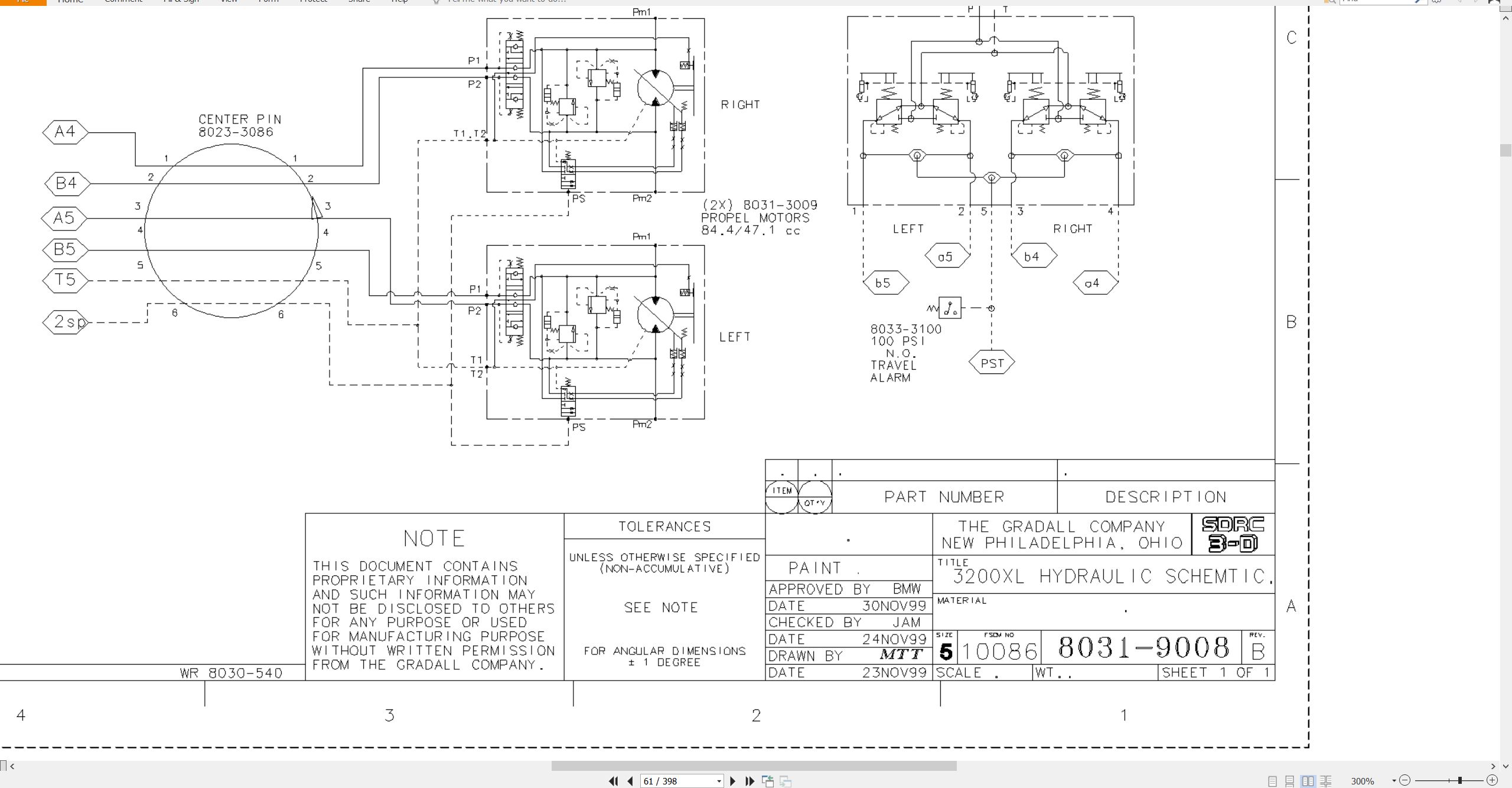
8031-9008 Hydraulic Schematic
8031-9004 Start-Up Procedure
RA64555 Rexroth Joystick Installation
MECHANICAL ADJUSTMENT
SM1512-002 Parker Hydraulic Motors Service Manual
75580 Ausco Brake Technical Page
29712 Boom Extension Installation
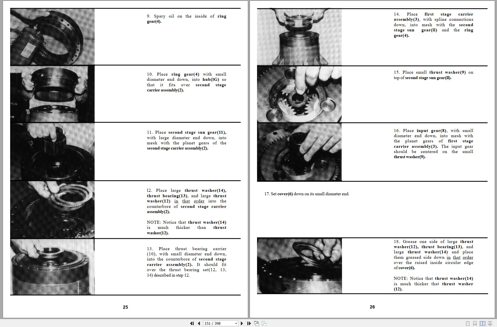
S6A Fairfield Torque-Hub Service Manual
ELECTRICAL
1M-128 Delco Remy Cranking Motor Service Manual
8046-3043 Cab Harness
8046-3042 Upper Harness
8046-3113 Engine Harness
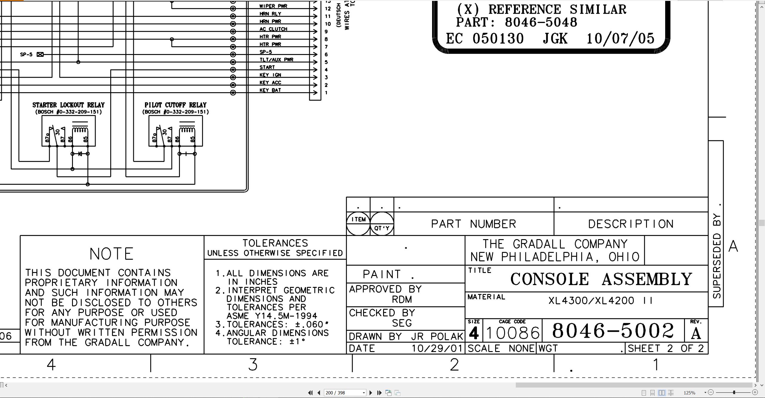
8046-5002 Console Assembly Wiring Diagram
CRAWLER
29635 XL Series Crawler Maintenance Manual
29302 Kayaba Service Manual
MISCELLANEOUS
HE92-2 EMI Safety Manual
20013 Gradall Safety Manual
XL3200HP Owner Operator Manual 31200147 2006.pdf (50 Pages)
Contents:
Introduction
General
Related Manuals & Decals
Operator Qualifications
Orientation
Pin Plate Location
Models Covered
Nomenclature
Nomenclature
Tool Kit
Safety Highlights
Decals
Decals Inside Cab
Decals Outside Cab
Serial No. Plates
Operator’s Cab
Seat Adjustment
Heater
Air Conditioner
Defrost
Ventilation
Wiper/Washer
12 Vdc Accessory Outlets
Control & Instrument Identification
Electronic Monitor
Checks & Services Before Starting Engine
Engine Operation
Starting John Deere Engine
Cold Weather Starting Aids
Normal Engine Operations
Auto Idle (Fuel Saving)
Stopping The Engine
Warm Up & Operational Checks
Adapter Attachment Installation
Use Your Crawler Properly
Crawler Controls
How To Operate The Crawler
Lifting & Positioning A Load
Precautions
General
Positioning Machine For A Lift
Planning A Lift
Recommended Lubricants & Capacities
Torque Chart
Lubrication & Maintenance Diagram
Securing Boom
Emergency Towing
If You Get Stuck
Loading And Securing Machine For Transport
Preservation & Storage
Excavator Hand Signals
Related Products
-
Gradall Wheeled Excavator XL4300II Operators Parts Service Technical Manual
30 USDSize: 355.36 MBFormat: PDFLanguage: EnglishBrand: GradallType of Machine: Rough-terrain Wheeled ExcavatorType of Manual: Combined Service Manual, Electrical Schematic, Hydraulic Schematic, Illustrated Parts Manual, Operators Manual, Parts Manual, Service Manual, Technical ManualModel: Gradall XL4300II Rough-terrain Wheeled Excavator
REALEASE :
REALEASE :
-
Gradall Wheeled Excavator XL4300V Operators Parts Service Manual
30 USDSize: 252.03 MBFormat: PDFLanguage: EnglishBrand: GradallType of Machine: Rough-terrain Wheeled ExcavatorType of Manual: Assembly Manual, Electrical Schematic, Hydraulic Schematic, Illustrated Parts Manual, Installation Instructions, Installation Parts Manual, Lubrication Chart, Maintenance Manual, Operator Manual, Safety Manual, Operators Instruction, Parts Manual, Service Supplement, User ManualModel: Gradall XL4300V Rough-terrain Wheeled Excavator
REALEASE :
REALEASE :
-
Gradall Wheeled Excavator XL3300V Operators Parts Service Manual
30 USDSize: 214.38 MBFormat: PDFLanguage: EnglishBrand: GradallType of Machine: Rough-terrain Wheeled ExcavatorType of Manual: Electrical Schematic, Hydraulic Schematic, Illustrated Parts Manual, Lubrication Chart, Operator Safety Manual, Parts Manual, Service SupplementModel: Gradall XL3300V Rough-terrain Wheeled Excavator
REALEASE :
REALEASE :
-
Gradall Wheeled Excavator XL5300 Operators Parts Service Manual
30 USDSize: 309.61 MBFormat: PDFLanguage: EnglishBrand: GradallType of Machine: Rough-terrain Wheeled ExcavatorType of Manual: Electrical Schematic, Hydraulic Schematic, Illustrated Parts Manual, Operator Manual, Safety Manual, Parts Manual, Service Manual, Service SupplementModel: Gradall XL5300 Rough-terrain Wheeled Excavator
REALEASE :
REALEASE :
-
Gradall Wheeled Excavator XL5300III Operators Parts Service Manual
30 USDSize: 311.43 MBFormat: PDFLanguage: EnglishBrand: GradallType of Machine: Rough-terrain Wheeled ExcavatorType of Manual: Electrical Schematic, Hydraulic Schematic, Illustrated Parts Manual, Lubrication Chart, Operator Manual, Safety Manual, Parts Manual, Service Manual, Service SupplementModel: Gradall XL5300III Rough-terrain Wheeled Excavator
REALEASE :
REALEASE :
-
Gradall Wheeled Excavator XL4300IICE Operators Service Manual 31200155 2006
30 USDSize: 130.81 MBFormat: PDFLanguage: EnglishBrand: GradallType of Machine: Rough-terrain Wheeled ExcavatorType of Manual: Combined Service Manual, Operators Manual, Hydraulic Schematic, Electrical SchematicModel: Gradall XL4300IICE 31200155, XL4300IICE 31200154 Rough-terrain Wheeled ExcavatorSerial Number: 0210017803Part Number: XL4300IICE 31200155, XL4300IICE 31200154Publication Date: 31200155 – 2006, 31200154 – 2005Number of Pages: 953 Pages
REALEASE :
REALEASE :
-
Gradall Wheeled Excavator XL5300V Operators Parts Service Manual
30 USDSize: 214.38 MBFormat: PDFLanguage: EnglishBrand: GradallType of Machine: Rough-terrain Wheeled ExcavatorType of Manual: Electrical Schematic, Hydraulic Schematic, Illustrated Parts Manual, Lubrication Chart, Operator Manual, Safety Manual, Parts Manual, Service SupplementModel: Gradall XL5300V Rough-terrain Wheeled Excavator
REALEASE :
REALEASE :
-
Gradall Wheeled Excavator XL4300 Operators Parts Service Manual
30 USDSize: 321.70 MBFormat: PDFLanguage: EnglishBrand: GradallType of Machine: Rough-terrain Wheeled ExcavatorType of Manual: Electrical Schematic, Hydraulic Schematic, Illustrated Parts Manual, Lubrication Chart, Operator Manual, Safety Manual, Parts Manual, Service Manual, Service SupplementModel: Gradall XL4300 Rough-terrain Wheeled Excavator
REALEASE :
REALEASE :