
10 ITEMSVIEW CART


Total: 445.00
Expert Support
Full Speed
100% Working
30 USD
List of Files:
XL4100III XL5100III Air Diagram 3540008.pdf (1 Pages)
XL4100III XL5100III Air Schematic 3540009.pdf (1 Pages)
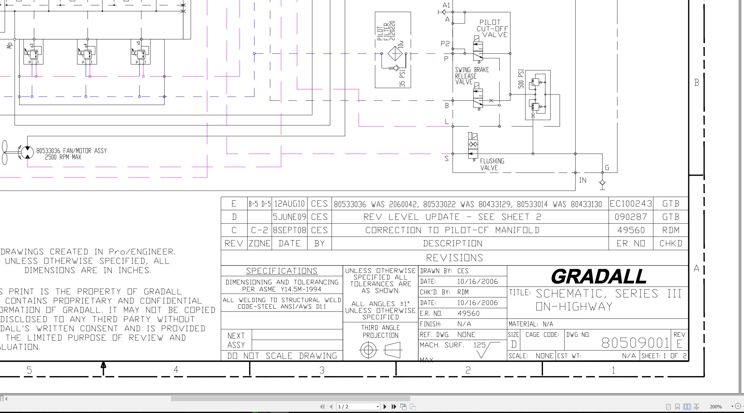
XL3100III XL3100 XL4100III XL5100III Hydraulic Schematic 80509001.pdf (2 Pages)
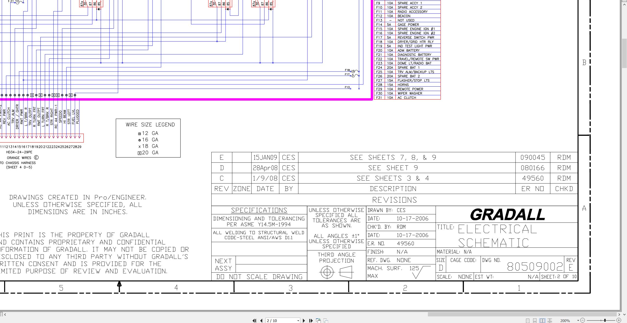
XL3100III XL3100 XL4100III XL5100III Electrical Schematic 80509002.pdf (10 Pages)
Series III XL3100III XL4100III XL5100III Illustrated Parts Manual 80854001 2026.pdf (864 Pages)
Contents:
80854001_AC_Series III Highway Speed Excavators_Parts Manual_3-2026
Effectivity Page
Table of Contents
Understanding Your Manual
Section 1 – Frame & Attaching Parts
Section 2 – Boom
Section 3 – Attachments
Section 4 – Engine & Attaching Parts
Section 5 – Drive Train
Section 6 – Cab
Section 7 – Controls
Section 8 – Hydraulic Circuits
Section 9 – Hydraulic Components
Section 10 – Electrical
Section 11 – Decals
Section 12 – Options
Recommended Spare Parts
Part Number Index
Series III XL3100III XL4100III XL5100III Operator Safety Manual 80854002 2024.pdf (166 Pages)
Contents:
Section 1 – General Safety Practices
1.1 Hazard Classification System
1.2 General Precautions
1.3 Operation Safety
1.4 Personal Protection Equipment
Section 2 – Pre-Operation and Controls
2.1 Pre-Operation Checks & Inspection
2.2 Walk-Around Inspection
2.3 Safety Decals
2.4 Undercarriage Cab Components
2.5 Undercarriage Cab Controls & Indicators
2.6 Upperstructure Cab Components
2.7 Upperstructure Cab Controls & Indicators
Section 3 – Operation
3.1 Travel Mode Engine Operation
3.2 Checks Before Undercarriage Operation
3.3 Travel Mode Brake System
3.4 Travel Mode Power Train
3.5 Travel Mode Engine Shutdown
3.6 Remote Control Preparation
3.7 Checks Before Remote Control Operation
3.8 Remote Mode Brake System
3.9 Remote Mode Power Train
3.10 Steering System
3.11 Typical Dig Cycle
3.12 Lifting & Placing a Load
3.13 Lift Capacity
3.14 Remote Mode Engine Shutdown
3.15 Return to Travel Mode
3.16 Parking the Excavator
3.17 Preservation & Storage
Section 4 – Attachments
4.1 Approved Attachments
4.2 Unapproved Attachments
4.3 Attachment Operation
4.4 Adapter Attachment Installation
Section 5 – Lubrication & Maintenance
5.1 Introduction
5.2 General Maintenance Instructions
5.3 Service & Maintenance Schedules
5.4 Undercarriage Lubrication Schedules
5.5 Upperstructure Lubrication Schedules
5.6 Operator Maintenance Instructions
Section 6 – Emergency Procedures
6.1 Loss Of Power
Section 7 – Specifications
7.1 Product Specifications
7.2 Torque Chart
7.3 Fuses
Pre-Operation Inspection Checklist
Index
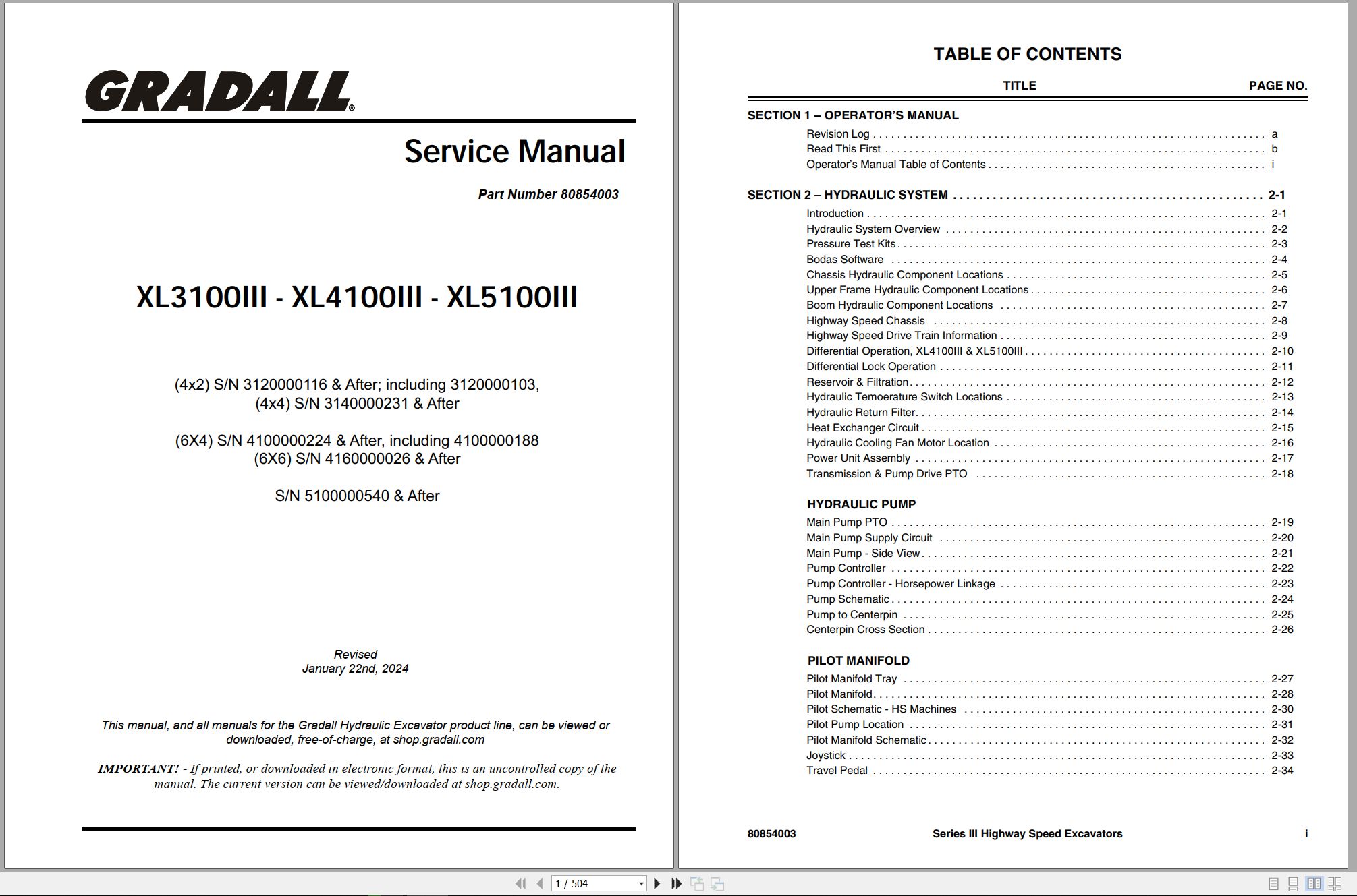
Series III XL3100III XL4100III XL5100III Service Manual 80854003 2024.pdf (504 Pages)
Contents:
Alphabetical Index
Operators Manual
80854002 F Series III Highway Speed Operation & Safety Manual 1-2024
Hydraulic Section
Hydraulic System Operation Manual
Hydraulic Pressure Adjustment Manual
Final Test Report
Shipping Inspection Checklist
Electrical Section
Gradall Bodas-Service Installation & Operation
On-Highway Electrical Switch Locations
Highway Speed Processor Operation
Mechanical Section
Tool Kit
Emergency Procedures
Pressure Test Kits
Recommended Lubricants & Capacities
Torque Chart
Boom Assembly Identification
Boom Cylinder Slide Pads
Boom Roller Adjustment
Boom Assembly Tool Eye & Adapter
Tool Cylinder & Auxiliary Circuit Hose Alignment
Transmission Oil Level
Axle Lubrication Information
Axle Oil Level
Transfer Case Lubrication
Air Dryer Maintenance
Clutch Adjustment Procedure
Transmission Shift Cable Adjustment
Brake Chambers
Mercedes Benz 900 Series Engine Oil Pan Drain Plugs
Fan Clutch Maintenance
Swing Transmission Lubricant Check & Refill Requirements
Swing Transmission Fill Illustration
Rear Axle Walking Beam Clearance
Remote Drive PTO Removal & Replacement
Torque Values & Tolerances for Lubricated English Bolts
Climate Control section
Gradall Highway Speed Climate Control System
System Safety
Hydraulic vs. Engine Drive
Typical A/C System Circuit
Compressor
Condenser
Receiver – Dryer
Expansion Valve
Evaporator
Thermostat
High Side/Low Side
Pressure Switch
Hydraulically Driven A/C Unit
Upper Climate Controls
AC/Heater Assembly – Cab Assembly
AC/Heater Valve Assembly – Highway Speed
Hydraulic Heater Unit – Highway Speed Excavator
Water Valve
Water Control Valve
Lower Climate Controls
AC System Receiver Dryers
AC System Receiver Dryers Directional Designation
R134a A/C Systems & Compressed Air
A/C System Moisture Contamination
4923354 (B) Chassis Cab Harness
4923322 (G) Chassis Harness
4923453 (C) Dash Harness
4923323 (C) Engine Harness
80509001 (E) Hydraulic Schematic
80509002 (E) Electrical Schematic
4923454 (A) Switch Panel Harness
80609016 (B) Hydraulic Fitting Torque Chart
4923464 (F) Upper Cab Harness
4923465 (E) Remote Upper Harness
0610178 (E) Upper Printed Circuit Board
0610176 (B) Chassis Printed Circuit Board
80889010 (A) Air Diagram (XL3100III)
80889011 (A) Air Schematic (XL3100III)
3540008 (A) Air Diagram (XL4100III & XL5100III)
3540009 (A) Air Schematic (XL4100III & XL5100III)
SIII Highway Speed Vendor Component XL3100 XL3100III to XL5100III Service Manual CLSM0100 2006.pdf (969 Pages)

REALEASE :
REALEASE :

REALEASE :
REALEASE :

REALEASE :
REALEASE :

REALEASE :
REALEASE :

REALEASE :
REALEASE :

REALEASE :
REALEASE :

REALEASE :
REALEASE :

REALEASE :
REALEASE :
 Automotive - Heavy Equipment - Truck & Bus - Forklift - Crane