
1 ITEMVIEW CART

Total: 20.00

Expert Support
Full Speed
100% Working
30 USD
List of Files:
XL4200II Illustrated Parts Manual 31200066 2005.pdf (322 Pages)
Contents:
Section 1 Frame And Attaching Parts
Section 2 Boom
Section 3 Attachments
Section 4 Engine and Attaching Parts
Section 5 Drive Train
Section 6 Cab
Section 7 Controls
Section 8 Hydraulic Circuit
Section 9 Hydraulic Components
Section 10 Electrical
Section 11 Decals
Section 12 Options
Section 13 Recommended Spare Parts
Section 14 Part Number Index
XL4200II Illustrated Parts Manual 31200161 2005.pdf (256 Pages)
Contents:
Section 1 Frame And Attaching Parts
Section 2 Boom
Section 3 Attachments
Section 4 Engine and Attaching Parts
Section 5 Drive Train
Section 6 Cab
Section 7 Controls
Section 8 Hydraulic Circuit
Section 9 Hydraulic Components
Section 10 Electrical
Section 11 Decals
Section 12 Options
Section 13 Recommended Spare Parts
Section 14 Part Number Index
XL4200II Illustrated Parts Manual 31200328 2013.pdf (252 Pages)
Contents:
Service Kits
Section 1 Frame & Attaching Parts
Figure 1-1 Frame Assembly
Figure 1-2 Crawler Illustrated Summary
Figure 1-3 Rotating Platform, L.H. View
Figure 1-4 Rotating Platform, R.H. View
Figure 1-5 Swing Bearing, Cradle, Hoist Cylinder Mounting & Lube System
Figure 1-6 Valve Cover
Figure 1-7 Engine Cover
Figure 1-8 Front Cover
Section 2 Boom
Figure 2-1 Boom Cradle
Figure 2-2 Main Boom Assembly
Figure 2-3 Telescope Boom Assembly
Figure 2-4 Roller Assemblies
Figure 2-5 Bucket Linkage
Section 3 Attachments
Figure 3-1 Conveyor Bucket, 2184mm
Section 4 Engine & Attaching Parts
Figure 4-1 Engine Assembly
Figure 4-2 John Deere Engine
Figure 4-3 Air Cleaner & Installation
Figure 4-4 Air Cleaner
Figure 4-5 Exhaust System
Figure 4-6 Fuel Tank Assembly
Figure 4-7 Oil Cooler, Radiator & Hoses
Section 5 Drive Train
Figure 5-1 Track Chain & Shoes
Figure 5-2 Track Roller
Figure 5-3 Carrier Roller
Figure 5-4 Front Idler Track Adjuster
Figure 5-5 Crawler Drive – Control
Figure 5-6 Crawler Drive – Hydraulic Motor
Figure 5-7 Crawler Drive – Gearbox
Section 6 Cab
Figure 6-1 Operators Cab
Figure 6-2 Operators Cab
Figure 6-3 Cab Door
Figure 6-4 Cab Interior Components
Figure 6-5 Cab Console
Figure 6-6 Cab Seat
Figure 6-7 Cab Heater & Installation
Figure 6-8 Pilot Cut-Off Assembly
Figure 6-9 Wiper-Washer Installation Components
Section 7 Controls
Figure 7-1 Joystick
Figure 7-2 Foot Pedals & Installation
Section 8 Hydraulic Circuits
Figure 8-1 Oil Supply to Pumps
Figure 8-2 Hydraulic Pressure to Control Valves
Figure 8-3 Main Valve to Pilot Manifold Hydraulic Hosing
Figure 8-4 Hydraulic Hosing to Joystick & Foot Operated Valves
Figure 8-5 Dump Circuit
Figure 8-6 Hoist Pilot
Figure 8-7 Boom Pilot
Figure 8-8 Tool Pilot
Figure 8-9 Swing & Swing Brake Pilot
Figure 8-10 Tilt & Auxiliary Pilot
Figure 8-11 Hoist Cylinder
Figure 8-12 Boom Cylinder
Figure 8-13 Tool Cylinder
Figure 8-14 Swing Motor
Figure 8-15 Tilt Motor
Figure 8-16 Upper Propelling
Figure 8-17 Center Pin Hosing
Figure 8-18 Drive Assembly Drain Hoses
Section 9 Hydraulic Components
Figure 9-1 Hoist Cylinder Assembly
Figure 9-2 Boom Cylinder Assembly
Figure 9-3 Tool Cylinder Assembly
Figure 9-4 Main Pump – Front
Figure 9-5 Main Pump – Rear
Figure 9-6 Pilot Manifold Valve Tray Hydraulic Components
Figure 9-7 Pilot Manifold
Figure 9-8 Main Hydraulic Control Valve
Figure 9-9 Main Hydraulic Control Valve – Spools & End Caps
Figure 9-10 Main Hydraulic Control Valve – Swing Section
Figure 9-11 Main Hydraulic Control Valve – Seal Kits
Figure 9-12 Hydraulic Reservoir Assembly
Figure 9-13 Swing Transmission Installation
Figure 9-14 Swing Transmission
Figure 9-15 Swing Motor
Figure 9-16 Swing Brake
Figure 9-17 Tilt Transmission Assembly
Figure 9-18 Tilt Transmission
Figure 9-19 Tilt Brake
Figure 9-20 Tilt Motor
Figure 9-21 Center Pin
Figure 9-22 Foot Operated Pedal Valve
Figure 9-23 Cold Start Valve
Figure 9-24 Hoist Limit Valve
Figure 9-25 Swing Reduction Valve
Section 10 Electrical
Figure 10-1 Batteries & Miscellaneous Electrical Components
Figure 10-2 Cab Console Circuit Board
Section 11 Decals
Figure 11-1 Decals
Section 12 Options
Figure 12-1 Air Conditioner Kit Installation Components
Figure 12-2 Air Conditioner Evaporator Kit Installation Components
Figure 12-3 Aux Boom Hoses for Greasing Installation Components
Figure 12-4 Floodlight Installation Components
Figure 12-5 Cold Start Installation Components
Figure 12-6 Cab Roof and Window Guard Installation
Recommended Spare Parts
Part Number Index
XL4200II Combined Service Manual 8041-4002 2006.pdf (582 Pages)
Contents:
8041-4002 XL4200II SERVICE MANUAL
OPERATOR INSTRUCTION
20142 Operation & Lube Manual
SCHEDULED MAINTENANCE
8090-9017 Critical Item Checklist
8041-9002 Final Test Report
HYDRAULIC SYSTEM OPERATION
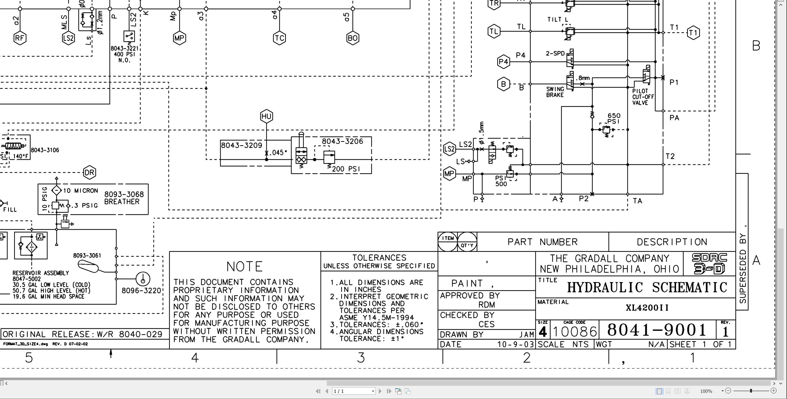
8041-9001 Hydraulic Schematic
8041-9003 Start-up Procedure
RDE93010-02-R Rexroth Main Pump
RDE92002-30 Rexroth Swing Pump
RDE91001-01-R Rexroth Swing Motor
RA64555 Rexroth Joystick
7-124 Char-Lynn Tilt Motor
MECHANICAL ADJUSTMENTS
SM1512-003 Parker Low Speed-High Torque Hyd Motor
Fairfield Swing Brake
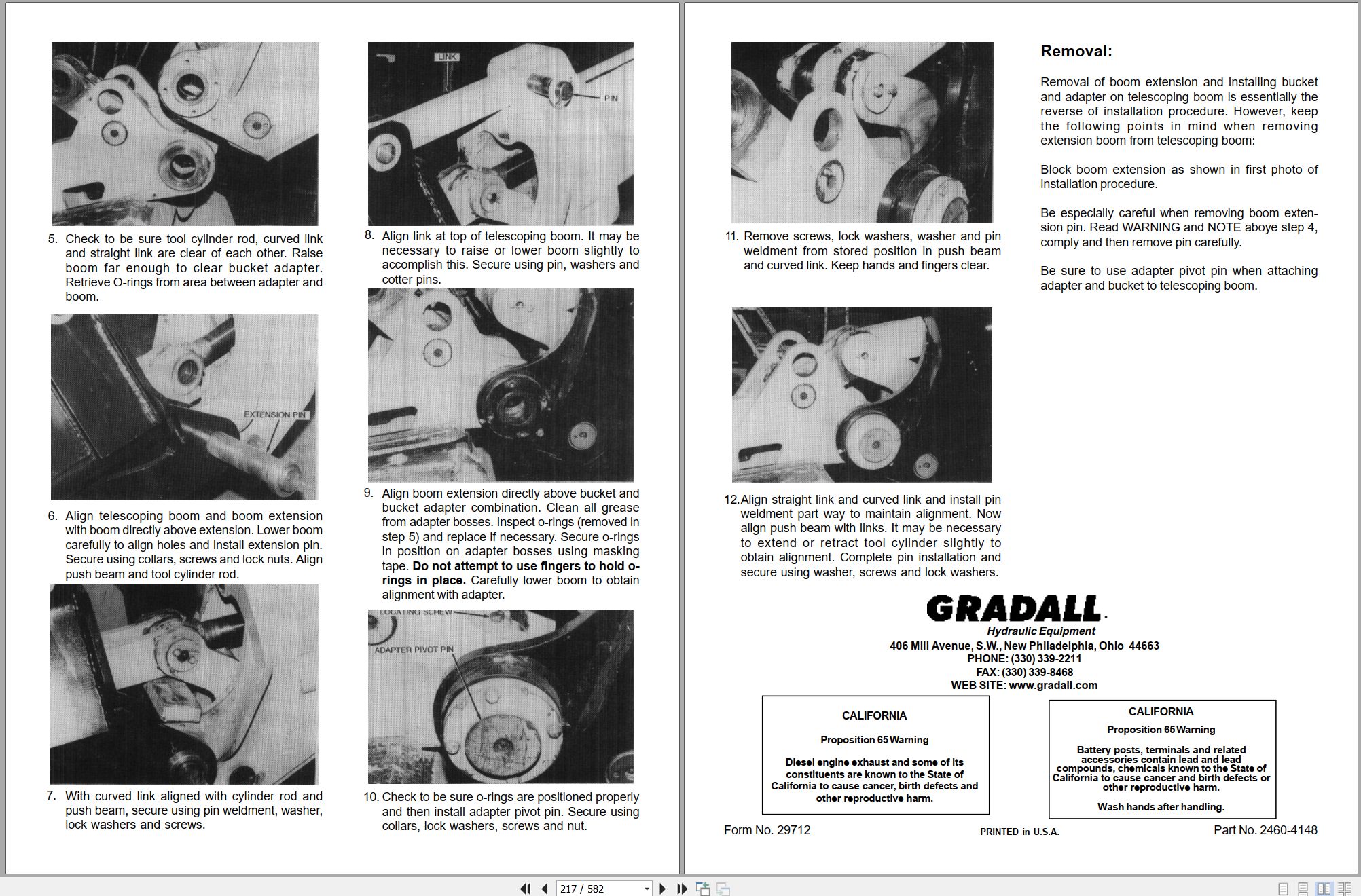
29712 Boom Extension Installation
S6A Fairfield Torque-Hub Service Manual
ELECTRICAL
1M-128 Delco Remy
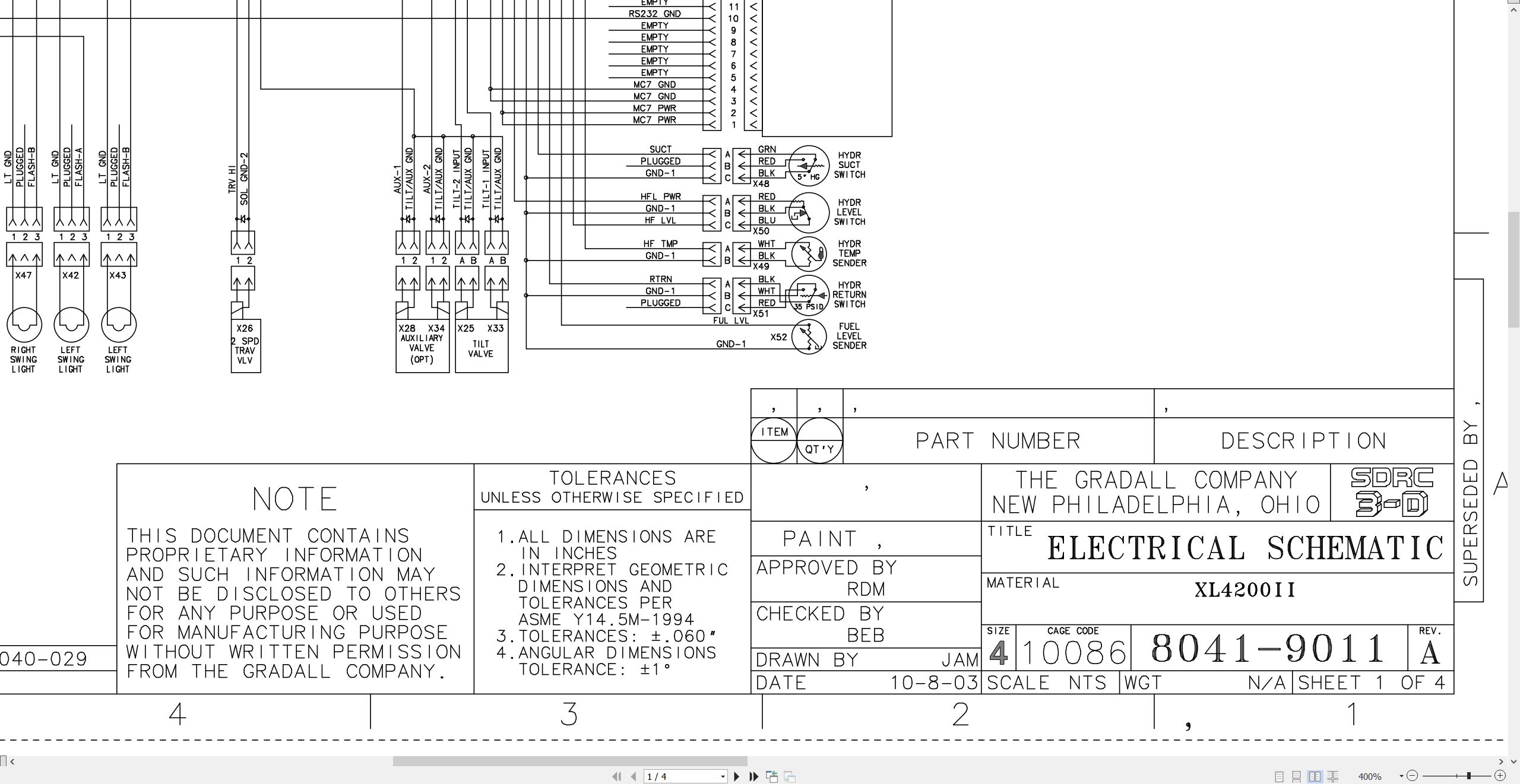
8041-9011 Electric Schematic
8046-3113 Engine Harness
8046-3043 Cab Harness
8046-5002 Console
8046-3036 EMU
DCMB Trojan Deep Cycle Battery Maintenance
125-189AA Prestolite Service Manual
CRAWLER
29302 Kayaba Service Manual
29635 XL Series Crawler Maintenance Manual
MISCELLANEOUS
HE92-2 EMI Safety Manual – 8060-3007.pdf
20013 Gradall Safety Manual
F114004 Donaldson Cyclopac Service Procedure
XL4200II Operators Manual 8041-4003 2004.pdf (60 Pages)
XL4200II Owner Operators Manual 8041-4006 2004.pdf (58 Pages)
XL4200II Illustrated Parts Manual 80414001 2024.pdf (378 Pages)
Contents:
Service Kits
Section 1 Frame & Attaching Parts
Figure 1-1 Frame Assembly
Figure 1-2 Crawler Illustrated Summary
Figure 1-3 Rotating Platform, L.H. View
Figure 1-4 Rotating Platform, R.H. View
Figure 1-5 Swing Bearing, Cradle, Hoist Cylinder Mounting & Lube System
Figure 1-6 Valve Cover
Figure 1-7 Engine Cover
Figure 1-8 Front Cover
Section 2 Boom
Figure 2-1 Boom Cradle
Figure 2-2 Main Boom Assembly
Figure 2-3 Telescope Boom Assembly
Figure 2-4 Roller Assemblies
Figure 2-5 Bucket Linkage
Section 3 Attachments
Figure 3-1 24†& 30†Excavating Buckets
Figure 3-2 36†& 42†Excavating Buckets
Figure 3-3 48†Excavating Bucket & 15†Trenching Bucket
Figure 3-4 18†& 28†Pavement Removal Bucket
Figure 3-5 40†Pavement Removal Bucket & 60†Ditching Bucket
Figure 3-6 28†Pavement Removal Bucket & 30†Ditching Bucket
Figure 3-7 Telestick
Figure 3-8 60†Ditching Bucket
Figure 3-9 66†Ditching Bucket
Figure 3-10 72†Ditching Bucket
Figure 3-11 66†Ditching Bucket & Guardrail Back Scraper
Figure 3-12 8’ Grading Blade & Single Tooth Ripper
Figure 3-13 4’ Boom Extension
Figure 3-14 6’ Boom Extension
Figure 3-15 8’ Boom Extension
Figure 3-16 12’ Boom Extension
Figure 3-17 Fixed Thumb Grapple
Figure 3-18 72†& 108†Dredging Buckets
Figure 3-19 66†& 72†Ditching Bucket w/Bolt-on Cutting Edge
Figure 3-20 60†Ditching Bucket w/Bolt-on Cutting Edge
Section 4 Engine & Attaching Parts
Figure 4-1 Engine Assembly
Figure 4-2 CE Engine Assembly
Figure 4-3 John Deere Engine
Figure 4-4 Air Cleaner & Installation
Figure 4-5 Air Cleaner
Figure 4-6 Exhaust System
Figure 4-7 Fuel Tank Assembly
Figure 4-8 Oil Cooler, Radiator & Hoses
Section 5 Drive Train
Figure 5-1 Track Chain & Shoes
Figure 5-2 Track Roller
Figure 5-3 Carrier Roller
Figure 5-4 Front Idler Track Adjuster
Figure 5-5 Crawler Drive Motor Assembly – Control
Figure 5-6 Crawler Drive Motor Assembly – Hydraulic Motor
Figure 5-7 Crawler Drive Motor Assembly – Gearbox
Section 6 Cab
Figure 6-1 Operators Cab
Figure 6-2 Operators Cab
Figure 6-3 Cab Door
Figure 6-4 Cab Interior Components
Figure 6-5 CE Cab Interior Components
Figure 6-6 Cab Console
Figure 6-7 Cab Seat
Figure 6-8 Cab Heater & Installation
Figure 6-9 Pilot Cut-Off Assembly
Figure 6-10 Wiper-Washer Installation Components
Section 7 Controls
Figure 7-1 Joystick
Figure 7-2 Foot Pedals & Installation
Section 8 Hydraulic Circuits
Figure 8-1 Oil Supply to Pumps
Figure 8-2 Hydraulic Pressure to Control Valves
Figure 8-3 Main Valve to Pilot Manifold Hydraulic Hosing
Figure 8-4 Hydraulic Hosing to Joystick & Foot Operated Valves
Figure 8-5 Dump Circuit
Figure 8-6 Hoist Pilot
Figure 8-7 Boom Pilot
Figure 8-8 Tool Pilot
Figure 8-9 Swing & Swing Brake Pilot
Figure 8-10 Tilt & Auxiliary Pilot
Figure 8-11 Hoist Cylinder
Figure 8-12 Hoist Tubes Replacement Kit
Figure 8-13 Boom Cylinder
Figure 8-14 Tool Cylinder
Figure 8-15 Swing Motor
Figure 8-16 Swing Tubes Replacement Kit
Figure 8-17 Tilt Motor
Figure 8-18 Upper Propelling
Figure 8-19 Center Pin Hosing
Figure 8-20 Drive Assembly Drain Hoses
Section 9 Hydraulic Components
Figure 9-1 Hoist Cylinder Assembly
Figure 9-2 Boom Cylinder Assembly
Figure 9-3 Tool Cylinder Assembly
Figure 9-4 Main Pump
Figure 9-5 Pilot Manifold Valve Tray Hydraulic Components
Figure 9-6 Pilot Manifold
Figure 9-7 Main Hydraulic Control Valve Assembly
Figure 9-8 Main Hydraulic Control Valve
Figure 9-9 Main Hydraulic Control Valve – Spools & End Caps
Figure 9-10 Main Hydraulic Control Valve – Swing Section
Figure 9-11 Main Hydraulic Control Valve – Seal Kits
Figure 9-12 Hydraulic Reservoir Assembly
Figure 9-13 Swing Transmission Assembly
Figure 9-14 Swing Drive Assembly
Figure 9-15 Swing Motor
Figure 9-16 Swing Brake
Figure 9-17 Tilt Transmission Assembly
Figure 9-18 Tilt Drive Assembly
Figure 9-19 Tilt Brake Assembly
Figure 9-20 Tilt Motor
Figure 9-21 Center Pin
Figure 9-22 Foot Operated Pedal Valve
Figure 9-23 Cold Start Valve
Figure 9-24 Swing Reduction Valve
Section 10 Electrical
Figure 10-1 Batteries & Miscellaneous Electrical Components
Figure 10-2 Cab Console Circuit Board
Section 11 Decals
Figure 11-1 Decals
Figure 11-2 CE Decals
Section 12 Options
Figure 12-1 Air Conditioner Kit Installation Components
Figure 12-2 Air Conditioning Evaporator Kit
Figure 12-3 AM/FM Radio & Antenna Installation Components
Figure 12-4 Auxiliary Fan
Figure 12-5 Auxiliary Hydraulic Valve Field Installation Components
Figure 12-6 Additional Battery Installation Components
Figure 12-7 Bucket Hold-Open Installation Components
Figure 12-8 Cold Start Installation Components
Figure 12-9 Engine Block Heater Installation Components
Figure 12-10 Floodlight Installation Components
Figure 12-11 H.I.D. Floodlight Installation Component
Figure 12-12 Figure 12-11 H.I.D. Floodlight Installation Component
Figure 12-13 Four-Line Hose Trough Installation Components
Figure 12-14 Vandal Cover Installation Components
Recommended Spare Parts
Part Number Index
XL4200II CE Combined Service Manual 80414007 2006.pdf (606 Pages)
Contents:
8041-4007 XL4200II CE SERVICE MANUAL
OPERATOR INSTRUCTION
20301 Operation & Lube Manual
SCHEDULED MAINTENANCE
8090-9017 Critical Checklist
8041-9013 Test Report
HYDRAULIC SYSTEM OPERATION
8041-4101 XL4200 II Hydraulic Troubleshooting Manual
8041-9014 Hydraulic Schematic
8041-9003 Start-up Procedure
RDE92500-6-R Rexroth Main Pump Repair
RDE92002-30 Rexroth Swing Pump
RDE91001-01-R Rexroth Swing Motor
RA64555 Rexroth Joystick
7-124 Char-Lynn Tilt Motor
MECHANICAL ADJUSTMENTS
SM1512-003 Parker Low Speed-High Torque Hyd Motor
29712 Boom Extension Installation
S6A Fairfield Torque-Hub Service Manual
ELECTRICAL
8041-4102 XL4200 II Electrical Manual
1M-128 Delco Remy
8041-9012 Electric Schematic
8046-3113 Engine Harness
8046-3043 Cab Harness
8046-3036 EMU
DCMB Trojan Deep Cycle Battery Maintenance
125-189AA Prestolite Service Manual
CRAWLER
29302 Kayaba Service Manual
29635 XL Series Crawler Maintenance Manual
MISCELLANEOUS
HE92-2 EMI Safety Manual
20013 Gradall Safety Manual
F114004 Donaldson Cyclopac Service Procedure
XL4200II XL4300II Technical Manual 80414111 2011.pdf (576 Pages)
Contents:
ELECTRICAL
XL4200II Electrical System Manual
XL4300II Electrical System Manual
Engine Diagnostic Trouble Codes
XL4300II BB-3 Control Panel
HYDRAULIC
Hydraulic System Operation
XL4200II Hydraulic Pressure Setting Manual
XL4300II Hydraulic Pressure Setting Manual (Troubleshooting Guide)
XL4200II Final Test Report
XL4300II Final Test Report
MECHANICAL
XL4300II Maintenance Manual
XL4200II Maintenance Manual
Product Support Information – A/C System Reciever Dryers
Product Support Information – A/C Systems & Compressed Air
Product Support Information – A/C System Moisture Contamination
Product Support Information – Fan Clutch Maintenance
Product Support Information – Swing Transmission Lubricant Check & Refill Requirements
XL4300II Transmission Service Manual (ZF)
XL4300II Axle Service Manual (ZF)
SCHEMATICS
XL4200II Hydraulic Schematic (80419001)
XL4200II Electrical Schematic (80419011)
XL4300II Hydraulic Schematic (80439002)
XL4300II Electrical Schematic (80439001)
XL4200II XL4210II Hydraulic Schematic 80419001.pdf (1 Pages)
XL4200II XL4210II Electrical Schematic 80419011.pdf (4 Pages)

REALEASE :
REALEASE :

REALEASE :
REALEASE :

REALEASE :
REALEASE :

REALEASE :
REALEASE :

REALEASE :
REALEASE :

REALEASE :
REALEASE :

REALEASE :
REALEASE :

REALEASE :
REALEASE :
Automotive - Heavy Equipment - Truck & Bus - Forklift - Crane