
0 ITEMSVIEW CART

✓
Expert Support
✓
Full Speed
✓
100% Working
Gradall Excavator XL4200IICE Illustrated Parts Manual
Size: 62.90 MB
Format: PDF
Language: English
Brand: Gradall
Type of Machine: Crawler Telescopic Excavator
Type of Manual: Illustrated Parts Manual, Parts Manual
Model: Gradall XL4200IICE Crawler Telescopic Excavator
30 USD
- Description
Description
List of Files:
XL4200IICE Illustrated Parts Manual 31200158 2005.pdf (240 Pages)
Contents:
Section 1 Frame And Attaching Parts
Section 2 Boom
Section 3 Attachments
Section 4 Engine and Attaching Parts
Section 5 Drive Train
Section 6 Cab
Section 7 Controls
Section 8 Hydraulic Circuit
Section 9 Hydraulic Components
Section 10 Electrical
Section 11 Decals
Section 12 Options
Section 13 Recommended Spare Parts
Section 14 Part Number Index
XL4200IICE Illustrated Parts Manual 31200291 2007.pdf (258 Pages)
Contents:
Service Kits
Section 1 Frame & Attaching Parts
Figure 1-1 Frame Assembly
Figure 1-2 Crawler Illustrated Summary
Figure 1-3 Rotating Platform, L.H. View
Figure 1-4 Rotating Platform, R.H. View
Figure 1-5 Swing Bearing, Cradle, Hoist Cylinder Mounting & Lube System
Figure 1-6 Valve Cover
Figure 1-7 Engine Cover
Figure 1-8 Front Cover
Section 2 Boom
Figure 2-1 Boom Cradle
Figure 2-2 Main Boom Assembly
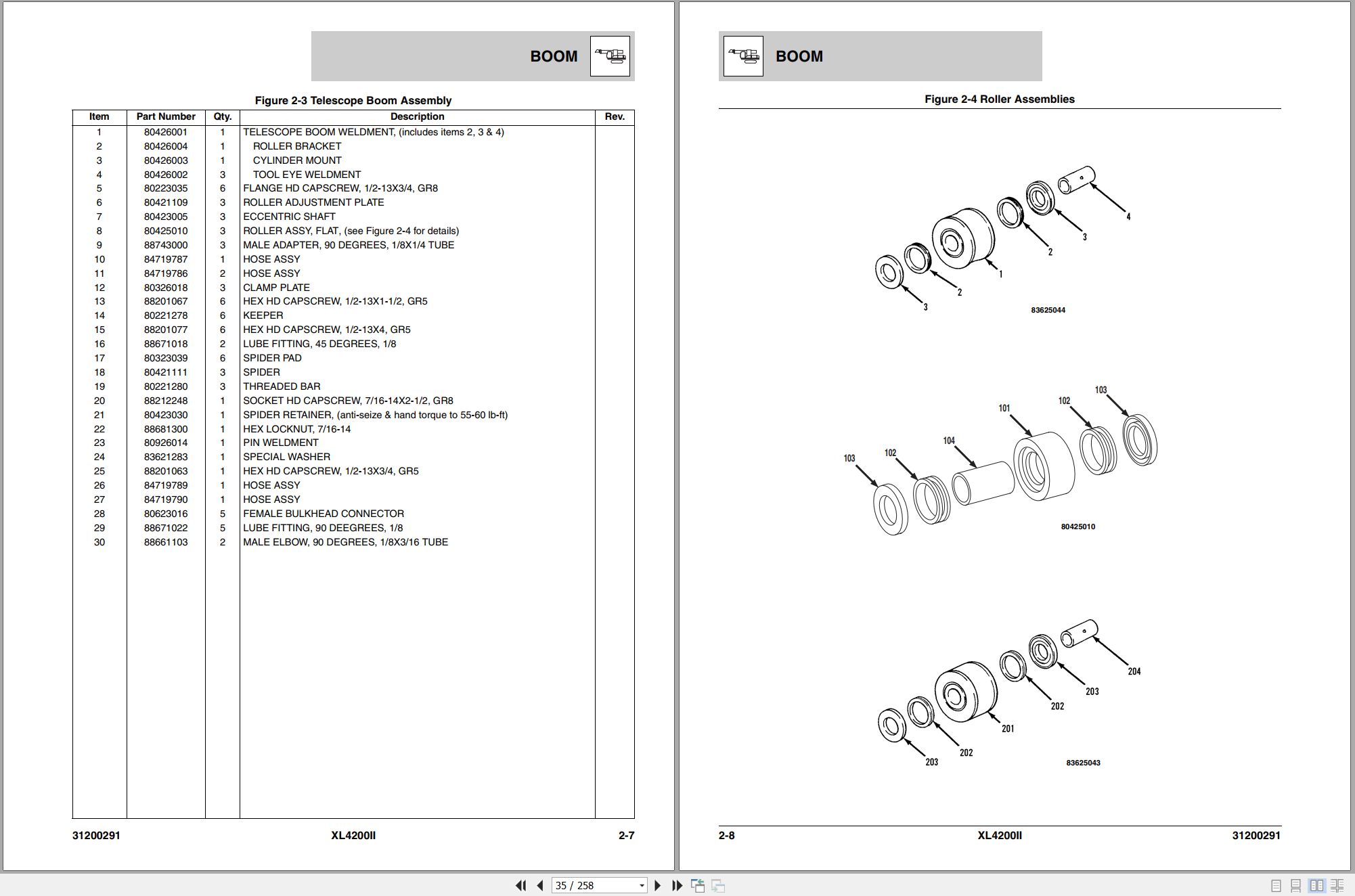
Figure 2-3 Telescope Boom Assembly
Figure 2-4 Roller Assemblies
Figure 2-5 Bucket Linkage
Section 3 Attachments
Figure 3-1 Conveyor Bucket – 2184mm
Figure 3-2 Conveyor Bucket – 2800mm
Section 4 Engine & Attaching Parts
Figure 4-1 CE Engine Assembly
Figure 4-2 John Deere Engine
Figure 4-3 Air Cleaner & Installation
Figure 4-4 Air Cleaner
Figure 4-5 Exhaust System
Figure 4-6 Fuel Tank Assembly
Figure 4-7 Oil Cooler, Radiator & Hoses
Section 5 Drive Train
Figure 5-1 Track Chain & Shoes
Figure 5-2 Track Roller
Figure 5-3 Carrier Roller
Figure 5-4 Front Idler Track Adjuster
Figure 5-5 Crawler Drive – Control
Figure 5-6 Crawler Drive – Hydraulic Motor
Figure 5-7 Crawler Drive – Gearbox
Section 6 Cab
Figure 6-1 Operators Cab
Figure 6-2 Operators Cab
Figure 6-3 Cab Door
Figure 6-4 CE Cab Interior Components
Figure 6-5 Cab Console
Figure 6-6 Cab Seat
Figure 6-7 Cab Heater & Installation
Figure 6-8 Pilot Cut-Off Assembly
Figure 6-9 Wiper-Washer Installation Components
Section 7 Controls
Figure 7-1 Joystick
Figure 7-2 Foot Pedals & Installation
Section 8 Hydraulic Circuits
Figure 8-1 Oil Supply to Pumps
Figure 8-2 Hydraulic Pressure to Control Valves
Figure 8-3 Main Valve to Pilot Manifold Hydraulic Hosing
Figure 8-4 Hydraulic Hosing to Joystick & Foot Operated Valves
Figure 8-5 Dump Circuit
Figure 8-6 Hoist Pilot
Figure 8-7 Boom Pilot
Figure 8-8 Tool Pilot
Figure 8-9 Swing & Swing Brake Pilot
Figure 8-10 Tilt & Auxiliary Pilot
Figure 8-11 Hoist Cylinder
Figure 8-12 Boom Cylinder
Figure 8-13 Tool Cylinder
Figure 8-14 Swing Motor
Figure 8-15 Tilt Motor
Figure 8-16 Upper Propelling
Figure 8-17 Center Pin Hosing
Figure 8-18 Drive Assembly Drain Hoses
Section 9 Hydraulic Components
Figure 9-1 Hoist Cylinder Assembly
Figure 9-2 Boom Cylinder Assembly
Figure 9-3 Tool Cylinder Assembly
Figure 9-4 Main Pump – Front
Figure 9-5 Main Pump – Rear
Figure 9-6 Pilot Manifold Valve Tray Hydraulic Components
Figure 9-7 Pilot Manifold
Figure 9-8 Main Hydraulic Control Valve
Figure 9-9 Main Hydraulic Control Valve – Spools & End Caps
Figure 9-10 Main Hydraulic Control Valve – Swing Section
Figure 9-11 Main Hydraulic Control Valve – Seal Kits
Figure 9-12 Hydraulic Reservoir Assembly
Figure 9-13 Swing Transmission Installation
Figure 9-14 Swing Transmission
Figure 9-15 Swing Motor
Figure 9-16 Swing Brake
Figure 9-17 Tilt Transmission Assembly
Figure 9-18 Tilt Transmission
Figure 9-19 Tilt Brake
Figure 9-20 Tilt Motor
Figure 9-21 Center Pin
Figure 9-22 Foot Operated Pedal Valve
Figure 9-23 Cold Start Valve
Figure 9-24 Hoist Limit Valve
Figure 9-25 Swing Reduction Valve
Section 10 Electrical
Figure 10-1 Batteries & Miscellaneous Electrical Components
Figure 10-2 Cab Console Circuit Board
Section 11 Decals
Figure 11-1 CE Decals
Section 12 Options
Figure 12-1 Air Conditioner Kit Installation Components
Figure 12-2 Air Conditioner Evaporator Kit Installation Components
Figure 12-3 AM/FM Radio & Antenna Installation Components
Figure 12-4 Cold Start Installation Components
Figure 12-5 Engine Block Heater Installation Components
Figure 12-6 Floodlight Installation Components
Figure 12-7 Lock Pin Installation
Figure 12-8 Four-Line Hose Trough Installation Components
Figure 12-9 Hoist Lock Installation
Recommended Spare Parts
Part Number Index
Related Products
-
Gradall Wheeled Excavator XL3300V Operators Parts Service Manual
30 USDSize: 214.38 MBFormat: PDFLanguage: EnglishBrand: GradallType of Machine: Rough-terrain Wheeled ExcavatorType of Manual: Electrical Schematic, Hydraulic Schematic, Illustrated Parts Manual, Lubrication Chart, Operator Safety Manual, Parts Manual, Service SupplementModel: Gradall XL3300V Rough-terrain Wheeled Excavator
REALEASE :
REALEASE :
-
Gradall Wheeled Excavator XL5300III Operators Parts Service Manual
30 USDSize: 311.43 MBFormat: PDFLanguage: EnglishBrand: GradallType of Machine: Rough-terrain Wheeled ExcavatorType of Manual: Electrical Schematic, Hydraulic Schematic, Illustrated Parts Manual, Lubrication Chart, Operator Manual, Safety Manual, Parts Manual, Service Manual, Service SupplementModel: Gradall XL5300III Rough-terrain Wheeled Excavator
REALEASE :
REALEASE :
-
Gradall Wheeled Excavator XL4300 Operators Parts Service Manual
30 USDSize: 321.70 MBFormat: PDFLanguage: EnglishBrand: GradallType of Machine: Rough-terrain Wheeled ExcavatorType of Manual: Electrical Schematic, Hydraulic Schematic, Illustrated Parts Manual, Lubrication Chart, Operator Manual, Safety Manual, Parts Manual, Service Manual, Service SupplementModel: Gradall XL4300 Rough-terrain Wheeled Excavator
REALEASE :
REALEASE :
-
Gradall Wheeled Excavator XL4300IICE Operators Service Manual 31200155 2006
30 USDSize: 130.81 MBFormat: PDFLanguage: EnglishBrand: GradallType of Machine: Rough-terrain Wheeled ExcavatorType of Manual: Combined Service Manual, Operators Manual, Hydraulic Schematic, Electrical SchematicModel: Gradall XL4300IICE 31200155, XL4300IICE 31200154 Rough-terrain Wheeled ExcavatorSerial Number: 0210017803Part Number: XL4300IICE 31200155, XL4300IICE 31200154Publication Date: 31200155 – 2006, 31200154 – 2005Number of Pages: 953 Pages
REALEASE :
REALEASE :
-
Gradall Wheeled Excavator XL5300 Operators Parts Service Manual
30 USDSize: 309.61 MBFormat: PDFLanguage: EnglishBrand: GradallType of Machine: Rough-terrain Wheeled ExcavatorType of Manual: Electrical Schematic, Hydraulic Schematic, Illustrated Parts Manual, Operator Manual, Safety Manual, Parts Manual, Service Manual, Service SupplementModel: Gradall XL5300 Rough-terrain Wheeled Excavator
REALEASE :
REALEASE :
-
Gradall Wheeled Excavator XL4300II Operators Parts Service Technical Manual
30 USDSize: 355.36 MBFormat: PDFLanguage: EnglishBrand: GradallType of Machine: Rough-terrain Wheeled ExcavatorType of Manual: Combined Service Manual, Electrical Schematic, Hydraulic Schematic, Illustrated Parts Manual, Operators Manual, Parts Manual, Service Manual, Technical ManualModel: Gradall XL4300II Rough-terrain Wheeled Excavator
REALEASE :
REALEASE :
-
Gradall Wheeled Excavator XL4300V Operators Parts Service Manual
30 USDSize: 252.03 MBFormat: PDFLanguage: EnglishBrand: GradallType of Machine: Rough-terrain Wheeled ExcavatorType of Manual: Assembly Manual, Electrical Schematic, Hydraulic Schematic, Illustrated Parts Manual, Installation Instructions, Installation Parts Manual, Lubrication Chart, Maintenance Manual, Operator Manual, Safety Manual, Operators Instruction, Parts Manual, Service Supplement, User ManualModel: Gradall XL4300V Rough-terrain Wheeled Excavator
REALEASE :
REALEASE :
-
Gradall Wheeled Excavator XL5300V Operators Parts Service Manual
30 USDSize: 214.38 MBFormat: PDFLanguage: EnglishBrand: GradallType of Machine: Rough-terrain Wheeled ExcavatorType of Manual: Electrical Schematic, Hydraulic Schematic, Illustrated Parts Manual, Lubrication Chart, Operator Manual, Safety Manual, Parts Manual, Service SupplementModel: Gradall XL5300V Rough-terrain Wheeled Excavator
REALEASE :
REALEASE :