
16 ITEMSVIEW CART


Total: 570.00
Expert Support
Full Speed
100% Working
30 USD
List of Files:
XL4210II Illustrated Parts Manual 31200050 2009.pdf (254 Pages)
Contents:
Section 1 Frame And Attaching Parts
Section 2 Boom
Section 3 Attachments
Section 4 Engine And Attaching Parts
Section 5 Drive Train
Section 6 Cab
Section 7 Controls
Section 8 Hydraulic Circuit
Section 9 Hydraulic Components
Section 10 Electrical
Section 11 Decals
Section 12 Options Section 13 Recommended Spare Parts
Section 14 Parts Number Index
XL4210II Illustrated Parts Manual 31200051 2009.pdf (264 Pages)
Contents:
Section 1 Frame And Attaching Parts
Section 2 Boom
Section 3 Attachments
Section 4 Engine And Attaching Parts
Section 5 Drive Train
Section 6 Cab
Section 7 Controls
Section 8 Hydraulic Circuit
Section 9 Hydraulic Components
Section 10 Electrical
Section 11 Decals
Section 12 Options Section 13 Recommended Spare Parts
Section 14 Parts Number Index
XL4210II (Remote Control) Illustrated Parts Manual 31200054 2009.pdf (246 Pages)
Contents:
Section 1 Frame And Attaching Parts
Section 2 Boom
Section 3 Attachments
Section 4 Engine And Attaching Parts
Section 5 Drive Train
Section 6 Cab
Section 7 Controls
Section 8 Hydraulic Circuit
Section 9 Hydraulic Components
Section 10 Electrical
Section 11 Decals
Section 12 Options Section 13 Recommended Spare Parts
Section 14 Parts Number Index
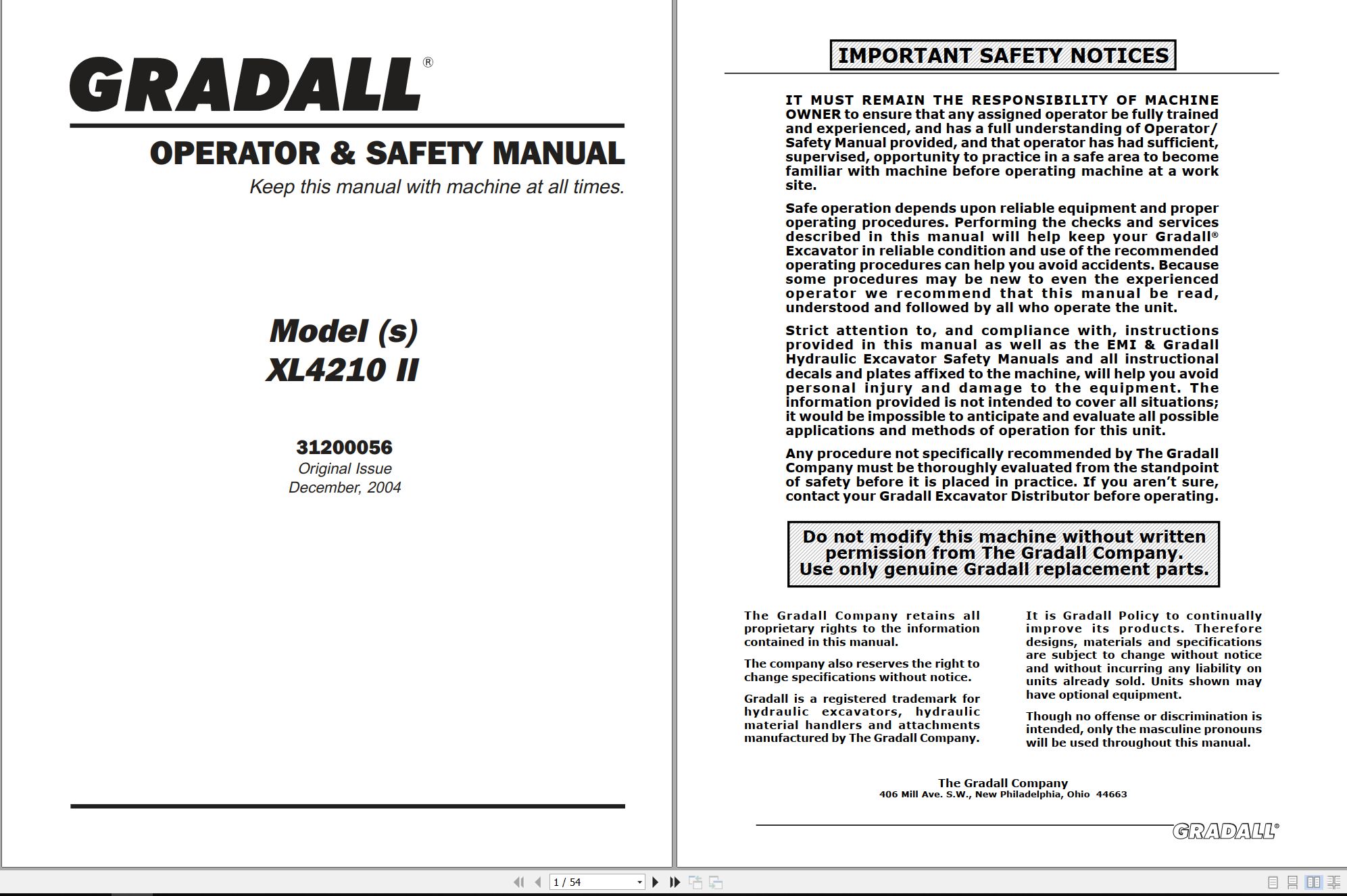
XL4210II Operator & Safety Manual 31200056 2004.pdf (54 Pages)
Contents:
Nomenclature
Tools
Safety
Decals
Serial Number Plates
Operators Cab
Engine Operation
Attachments
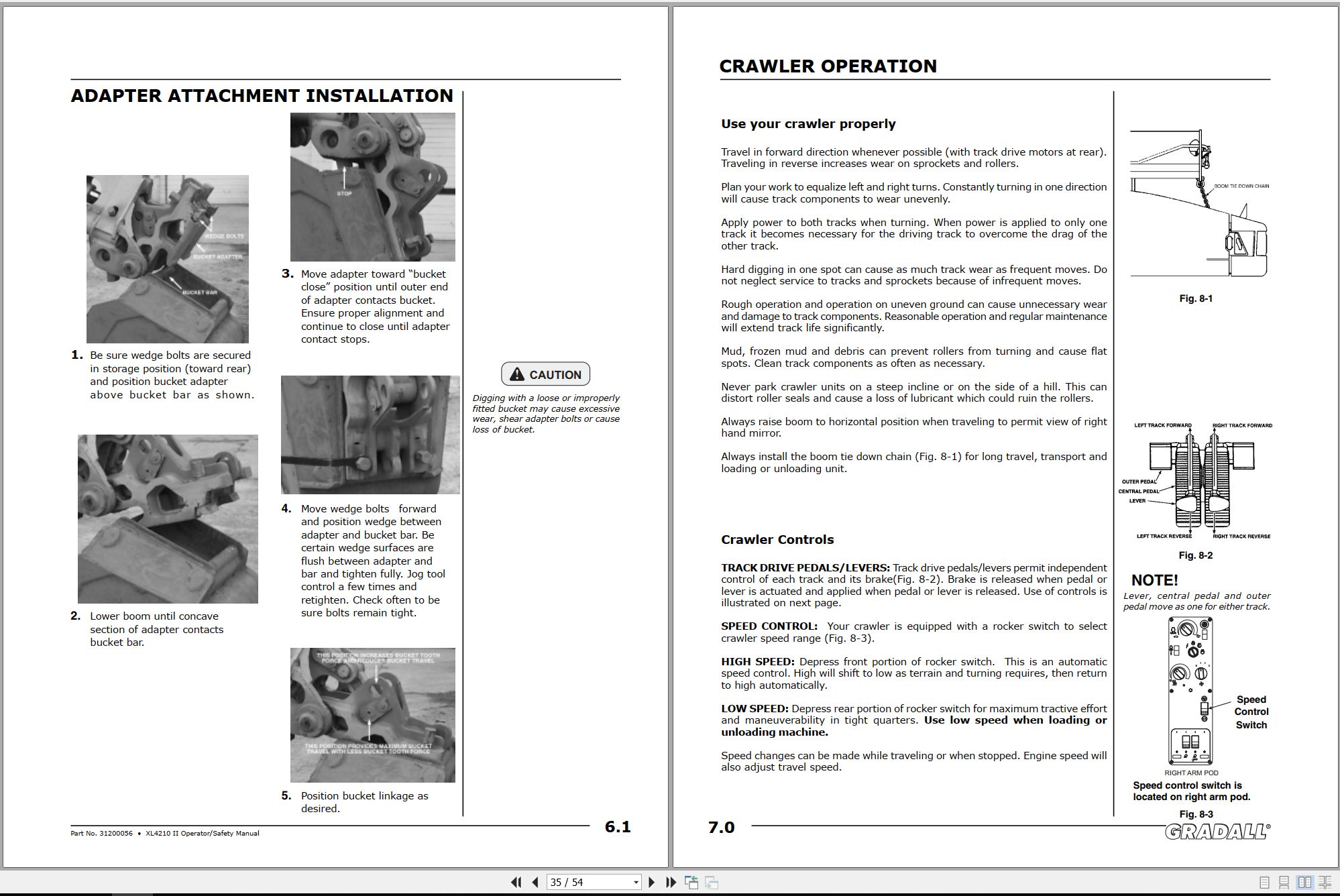
Crawler Operation
Operator Control Patterns
Typical Digging Cycle
Maintenance And Lubrication Diagram
Recommended Lubricants And Capacities
Torque Chart
Loading And Securing For Transport
If You Get Stuck
Preservation And Storage
Excavator Hand Signals
XL4210II Combined Service Manual 31200057 2006.pdf (577 Pages)
Contents:
XL4210 COMBINED SERVICE MANUAL
OPERATOR INSTRUCTION
31200056 XL4210II Excavator Operator/Safety Manual
SCHEDULED MAINTENANCE
8090-9017 Critical Item Check Sheet
8041-9016 Final Test Report
8041-9015 Final Test Report
HYDRAULIC SYSTEM OPERATION
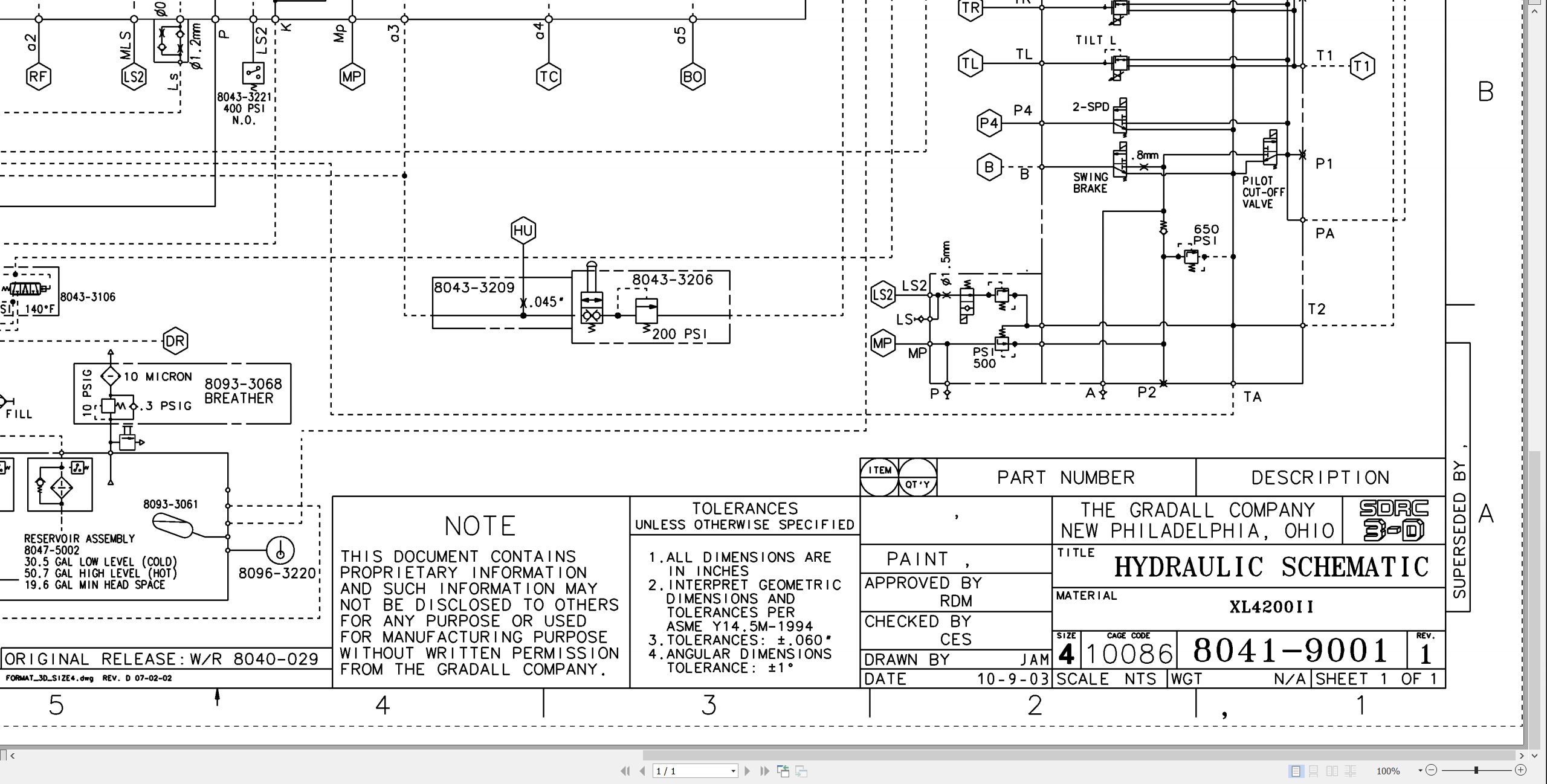
8041-9001 Hydraulic Schematic
8041-9003 Start-Up Procedure
RDE93010-02-R Rexroth Main Pump
RDE92002-30 Rexroth Swing Pump
RDE91001-01-R Rexroth Swing Motor
RA64555 Rexroth Joystick
7-124 Char-Lynn Tilt Motor
MECHANICAL ADJUSTMENTS
SM1512-003 Parker Low Speed-High Torque Hyd Motor
29712 Boom Extension Installation Manual
S6A Fairfield Torque-Hub Service Manual
ELECTRICAL
1M-128 Delco Remy Booklet 28-Mt Cranking Motor Service Manual
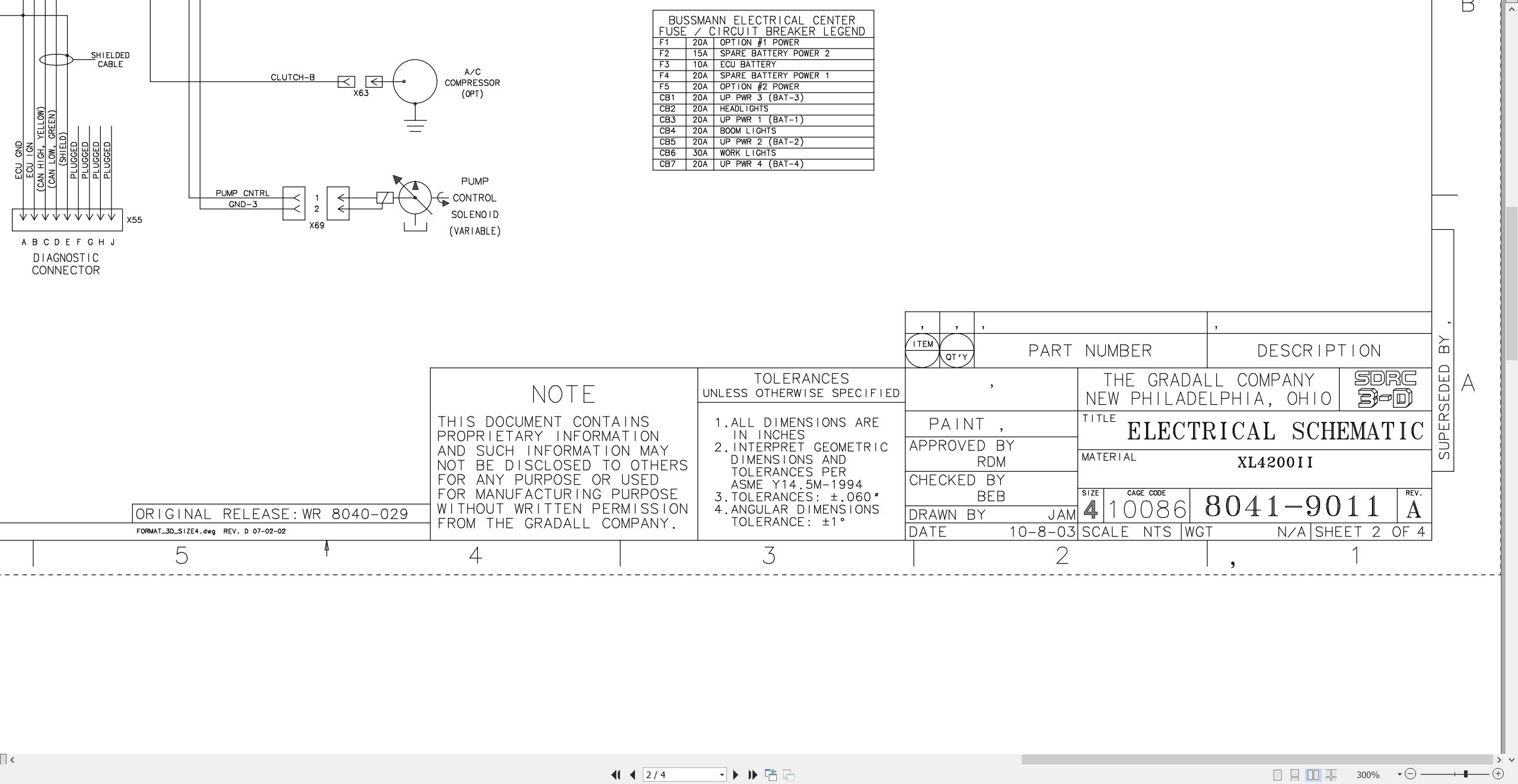
8041-9011 Electrical Schematic
8046-3113 Engine Harness
8046-3043 Cab Harness
8046-5002 Console Assembly Wiring Diagram
8046-3036 EMU – John Deere Tier II
DCMB
125-189AA Prestolite Service Manual MA-MR-HC Alternators
CRAWLER
29302 Kayaba Service Manual
29635 XL Series Crawler Maintenance Manual
MISCELLANEOUS
F114004 Donaldson Cyclopac Service Procedure
20013 Gradall Safety Manual
HE92-2 EMI Safety Manual
XL4210II Illustrated Parts Manual 31200096 2009.pdf (234 Pages)
Contents:
Section 1 Frame And Attaching Parts
Section 2 Boom
Section 3 Attachments
Section 4 Engine And Attaching Parts
Section 5 Drive Train
Section 6 Cab
Section 7 Controls
Section 8 Hydraulic Circuit
Section 9 Hydraulic Components
Section 10 Electrical
Section 11 Decals
Section 12 Options Section 13 Recommended Spare Parts
Section 14 Parts Number Index
XL4210II Illustrated Parts Manual 31200132 2009.pdf (238 Pages)
Contents:
Section 1 Frame And Attaching Parts
Section 2 Boom
Section 3 Attachments
Section 4 Engine And Attaching Parts
Section 5 Drive Train
Section 6 Cab
Section 7 Controls
Section 8 Hydraulic Circuit
Section 9 Hydraulic Components
Section 10 Electrical
Section 11 Decals
Section 12 Options Section 13 Recommended Spare Parts
Section 14 Parts Number Index
XL4210II Illustrated Parts Manual 31200134 2013.pdf (238 Pages)
Contents:
Section 1 Frame And Attaching Parts
Section 2 Boom
Section 3 Attachments
Section 4 Engine And Attaching Parts
Section 5 Drive Train
Section 6 Cab
Section 7 Controls
Section 8 Hydraulic Circuit
Section 9 Hydraulic Components
Section 10 Electrical
Section 11 Decals
Section 12 Options Section 13 Recommended Spare Parts
Section 14 Parts Number Index
XL4210II Illustrated Parts Manual 31200140 2009.pdf (238 Pages)
Contents:
Section 1 Frame And Attaching Parts
Section 2 Boom
Section 3 Attachments
Section 4 Engine And Attaching Parts
Section 5 Drive Train
Section 6 Cab
Section 7 Controls
Section 8 Hydraulic Circuit
Section 9 Hydraulic Components
Section 10 Electrical
Section 11 Decals
Section 12 Options Section 13 Recommended Spare Parts
Section 14 Parts Number Index
XL4210II Illustrated Parts Manual 31200159 2009.pdf (238 Pages)
Contents:
Section 1 Frame And Attaching Parts
Section 2 Boom
Section 3 Attachments
Section 4 Engine And Attaching Parts
Section 5 Drive Train
Section 6 Cab
Section 7 Controls
Section 8 Hydraulic Circuit
Section 9 Hydraulic Components
Section 10 Electrical
Section 11 Decals
Section 12 Options Section 13 Recommended Spare Parts
Section 14 Parts Number Index
XL4210II Illustrated Parts Manual 31200165 2009.pdf (238 Pages)
Contents:
Section 1 Frame And Attaching Parts
Section 2 Boom
Section 3 Attachments
Section 4 Engine And Attaching Parts
Section 5 Drive Train
Section 6 Cab
Section 7 Controls
Section 8 Hydraulic Circuit
Section 9 Hydraulic Components
Section 10 Electrical
Section 11 Decals
Section 12 Options Section 13 Recommended Spare Parts
Section 14 Parts Number Index
XL4210II Illustrated Parts Manual 31200167.pdf (236 Pages)
Contents:
Section 1 Frame And Attaching Parts
Section 2 Boom
Section 3 Attachments
Section 4 Engine And Attaching Parts
Section 5 Drive Train
Section 6 Cab
Section 7 Controls
Section 8 Hydraulic Circuit
Section 9 Hydraulic Components
Section 10 Electrical
Section 11 Decals
Section 12 Options Section 13 Recommended Spare Parts
Section 14 Parts Number Index
XL4210II Illustrated Parts Manual 31200168 2009.pdf (244 Pages)
Contents:
Section 1 Frame And Attaching Parts
Section 2 Boom
Section 3 Attachments
Section 4 Engine And Attaching Parts
Section 5 Drive Train
Section 6 Cab
Section 7 Controls
Section 8 Hydraulic Circuit
Section 9 Hydraulic Components
Section 10 Electrical
Section 11 Decals
Section 12 Options Section 13 Recommended Spare Parts
Section 14 Parts Number Index
XL4210II Illustrated Parts Manual 31200198 2009.pdf (242 Pages)
Contents:
31200198 XL4210II Parts Manual
Cover Page
Effectivity Page
Table of Contents
Service Kits
Section 1 Frame & Attaching Parts
Figure 1-1 Frame Assembly
Figure 1-2 Crawler Illustrated Summary
Figure 1-3 Rotating Platform, L.H. View
Figure 1-4 Rotating Platform, R.H. View
Figure 1-5 Swing Bearing, Cradle, Hoist Cylinder Mounting Pins & Lube System
Section 2 Boom
Figure 2-1 Boom Cradle
Figure 2-2 Main Boom Assembly
Figure 2-3 Telescope Boom Assembly
Figure 2-4 Roller Assemblies
Figure 2-5 Boom Hood and Stabilizer Mounting
Section 3 Attachments
Figure 3-1 6’ Boom Extension
Figure 3-2 Rammer S27 Hammer Installation
Section 4 Engine & Attaching Parts
Figure 4-1 Engine Assembly
Figure 4-2 John Deere Engine
Figure 4-3 Air Cleaner & Installation
Figure 4-4 Air Cleaner Assembly
Figure 4-5 Exhaust System
Figure 4-6 Fuel Tank
Figure 4-7 Oil Cooler, Radiator & Hoses
Section 5 Drive Train
Figure 5-1 Track Chain & Shoes
Figure 5-2 Track Roller Assembly
Figure 5-3 Carrier Roller Assembly
Figure 5-4 Front Idler Track Adjuster Assembly
Figure 5-5 Crawler Drive Control Assembly
Figure 5-6 Crawler Drive Hydraulic Motor Assembly
Figure 5-7 Crawler Drive Gearbox Assembly
Section 6 Cab
Figure 6-4 Cab Console
Section 7 Controls
Figure 7-1 Joystick Assembly
Figure 7-2 Foot Pedals & Installation
Section 8 Hydraulic Circuits
Figure 8-1 Oil Supply to Pumps
Figure 8-2 Hydraulic Pressure to Control Valves
Figure 8-3 Main Valve to Pilot Manifold Hydraulic Hosing
Figure 8-4 Hydraulic Hosing to Joystick & Foot Operated Valves
Figure 8-5 Dump Circuit
Figure 8-6 Hoist Pilot Hydraulic Circuit
Figure 8-7 Boom Pilot Hydraulic Circuit
Figure 8-8 Tool Pilot Hydraulic Circuit
Figure 8-9 Swing & Swing Brake Pilot Hydraulic Circuit
Figure 8-10 Tilt Pilot Hydraulic Circuit
Figure 8-11 Hoist Cylinder Hydraulic Circuit
Figure 8-12 Boom Cylinder Hydraulic Circuit
Figure 8-13 Tool Cylinder Hydraulic Circuit
Figure 8-14 Auxiliary Hydraulic Circuit
Figure 8-15 Swing Motor Hydraulic Circuit
Figure 8-16 Tilt Motor Hydraulic Circuit
Figure 8-17 Upper Propelling Hydraulic Circuit
Figure 8-18 Center Pin Hosing
Figure 8-19 Drive Assembly Drain Hoses
Section 9 Hydraulic Components
Figure 9-1 Hoist Cylinder Assembly
Figure 9-2 Boom Cylinder Assembly
Figure 9-3 Tool Cylinder Assembly
Figure 9-4 Main Pump Assembly
Figure 9-5 Main Pump Assembly
Figure 9-6 Pilot Manifold Valve Tray Hydraulic Components
Figure 9-7 Pilot Manifold Assembly
Figure 9-8 Main Hydraulic Control Valve Assembly
Figure 9-9 Main Hydraulic Control Valve Assembly
Figure 9-10 Main Hydraulic Control Valve Assembly
Figure 9-11 Main Hydraulic Control Valve Seal Kits
Figure 9-12 Hydraulic Reservoir Assembly
Figure 9-13 Swing Transmission Installation
Figure 9-14 Swing Transmission Assembly
Figure 9-15 Swing Motor Assembly
Figure 9-16 Swing Brake Assembly
Figure 9-17 Tilt Transmission Assembly
Figure 9-18 Tilt Brake
Figure 9-19 Center Pin Assembly
Figure 9-20 Foot Operated Pedal Valve Assembly
Figure 9-21 Cold Start Valve Assembly
Figure 9-22 Hoist Limit Valve Assembly
Figure 9-23 Swing Reduction Valve Assembly
Section 10 Electrical
Figure 10-1 Batteries & Miscellaneous Electrical Components
Figure 10-2 Cab Console Circuit Board
Section 11 Decals
Figure 11-1 Decals
Section 12 Options
Figure 12-1 Floodlight Installation Components
Figure 12-2 Auxiliary Hydraulic Option
Figure 12-3 Air Conditioner Kit Installation Components
Figure 12-4 Air Conditioner Evaporator Kit Installation Components
Figure 12-5 Cab Roof and Window Guard Installation
Figure 12-6 Auxiliary Fan Installation
Figure 12-7 Fire Resistant Hydraulic Fluid
Figure 12-8 6’ Boom Extension Hose Installation
Recommended Spare Parts
Part Number Index
XL4210II Illustrated Parts Manual 31200215 2009.pdf (244 Pages)
Contents:
XL4210II Parts Manual T#240793
Effectivity Page
Table of Contents
Service Kits
Section 1 Frame & Attaching Parts
Figure 1-1 Frame Assembly
Figure 1-2 Crawler Illustrated Summary
Figure 1-3 Rotating Platform, L.H. View
Figure 1-4 Rotating Platform, R.H. View
Figure 1-5 Swing Bearing, Cradle, Hoist Cylinder Mounting Pins & Lube System
Section 2 Boom
Figure 2-1 Boom Cradle
Figure 2-2 Main Boom Assembly
Figure 2-3 Telescope Boom Assembly
Figure 2-4 Roller Assemblies
Figure 2-5 Boom Hood and Stabilizer Mounting
Section 3 Attachments
Figure 3-1 Bucket Linkage
Figure 3-2 8’ Boom Extension
Figure 3-3 Hammer Installation Components
Section 4 Engine & Attaching Parts
Figure 4-1 Engine Assembly
Figure 4-2 John Deere Engine
Figure 4-3 Air Cleaner & Installation
Figure 4-4 Air Cleaner Assembly
Figure 4-5 Exhaust System
Figure 4-6 Fuel Tank
Figure 4-7 Oil Cooler, Radiator & Hoses
Section 5 Drive Train
Figure 5-1 Track Chain & Shoes
Figure 5-2 Track Roller Assembly
Figure 5-3 Carrier Roller Assembly
Figure 5-4 Front Idler Track Adjuster Assembly
Figure 5-5 Crawler Drive Control Assembly
Figure 5-6 Crawler Drive Hydraulic Motor Assembly
Figure 5-7 Crawler Drive Gearbox Assembly
Section 6 Cab
Figure 6-6 Cab Interior Components
Section 7 Controls
Figure 7-1 Joystick Assembly
Figure 7-2 Foot Pedals & Installation
Section 8 Hydraulic Circuits
Figure 8-1 Oil Supply to Pumps
Figure 8-2 Hydraulic Pressure to Control Valves
Figure 8-3 Main Valve to Pilot Manifold Hydraulic Hosing
Figure 8-4 Hydraulic Hosing to Joystick & Foot Operated Valves
Figure 8-5 Dump Circuit
Figure 8-6 Hoist Pilot Hydraulic Circuit
Figure 8-7 Boom Pilot Hydraulic Circuit
Figure 8-8 Tool Pilot Hydraulic Circuit
Figure 8-9 Swing & Swing Brake Pilot Hydraulic Circuit
Figure 8-10 Tilt Pilot Hydraulic Circuit
Figure 8-11 Hoist Cylinder Hydraulic Circuit
Figure 8-12 Boom Cylinder Hydraulic Circuit
Figure 8-13 Tool Cylinder Hydraulic Circuit
Figure 8-14 Auxiliary Hydraulic Circuit
Figure 8-15 Swing Motor Hydraulic Circuit
Figure 8-16 Tilt Motor Hydraulic Circuit
Figure 8-17 Upper Propelling Hydraulic Circuit
Figure 8-18 Center Pin Hosing
Figure 8-19 Drive Assembly Drain Hoses
Section 9 Hydraulic Components
Figure 9-1 Hoist Cylinder Assembly
Figure 9-2 Boom Cylinder Assembly
Figure 9-3 Tool Cylinder Assembly
Figure 9-4 Main Pump Assembly
Figure 9-5 Main Pump Assembly
Figure 9-6 Pilot Manifold Valve Tray Hydraulic Components
Figure 9-7 Pilot Manifold Assembly
Figure 9-8 Main Hydraulic Control Valve Assembly
Figure 9-9 Main Hydraulic Control Valve Assembly
Figure 9-10 Main Hydraulic Control Valve Assembly
Figure 9-11 Main Hydraulic Control Valve Seal Kits
Figure 9-12 Hydraulic Reservoir Assembly
Figure 9-13 Swing Transmission Installation
Figure 9-14 Swing Transmission Assembly
Figure 9-15 Swing Motor Assembly
Figure 9-16 Swing Brake Assembly
Figure 9-17 Tilt Transmission Assembly
Figure 9-18 Tilt Brake
Figure 9-19 Center Pin Assembly
Figure 9-20 Foot Operated Pedal Valve Assembly
Figure 9-21 Cold Start Valve Assembly
Figure 9-22 Hoist Limit Valve Assembly
Figure 9-23 Swing Reduction Valve Assembly
Section 10 Electrical
Figure 10-1 Batteries & Miscellaneous Electrical Components
Figure 10-2 Cab Console Circuit Board
Section 11 Decals
Figure 11-1 Decals
Section 12 Options
Figure 12-1 Floodlight Installation Components
Figure 12-2 Auxiliary Hydraulic Option
Figure 12-3 Air Conditioner Kit Installation Components
Figure 12-4 Air Conditioner Evaporator Kit Installation Components
Figure 12-5 Cab Roof and Window Guard Installation
Figure 12-6 Auxiliary Fan Installation
Figure 12-7 Fire Resistant Hydraulic Fluid
Figure 12-8 8’ Extension Hose Installation
Recommended Spare Parts
Part Number Index
XL4210II Illustrated Parts Manual 31200234 2009.pdf (238 Pages)
Contents:
XL4210II Parts Manual T#242416
Effectivity Page
Table of Contents
Service Kits
Section 1 Frame & Attaching Parts
Figure 1-1 Frame Assembly
Figure 1-2 Crawler Illustrated Summary
Figure 1-3 Rotating Platform, L.H. View
Figure 1-4 Rotating Platform, R.H. View
Figure 1-5 Swing Bearing, Cradle, Hoist Cylinder Mounting Pins & Lube System
Section 2 Boom
Figure 2-1 Boom Cradle
Figure 2-2 Main Boom Assembly
Figure 2-3 Telescope Boom Assembly
Figure 2-4 Roller Assemblies
Figure 2-5 Boom Hood and Stabilizer Mounting
Section 3 Attachments
Figure 3-1 Rammer S27 Hammer Installation
Figure 3-2 Bucket Linkage
Section 4 Engine & Attaching Parts
Figure 4-1 Engine Assembly
Figure 4-2 John Deere Engine
Figure 4-3 Air Cleaner & Installation
Figure 4-4 Air Cleaner Assembly
Figure 4-5 Exhaust System
Figure 4-6 Fuel Tank
Figure 4-7 Oil Cooler, Radiator & Hoses
Section 5 Drive Train
Figure 5-1 Track Chain & Shoes
Figure 5-2 Track Roller Assembly
Figure 5-3 Carrier Roller Assembly
Figure 5-4 Front Idler Track Adjuster Assembly
Figure 5-5 Crawler Drive Control Assembly
Figure 5-6 Crawler Drive Hydraulic Motor Assembly
Figure 5-7 Crawler Drive Gearbox Assembly
Section 6 Cab
Figure 6-4 Cab Console
Section 7 Controls
Figure 7-1 Joystick Assembly
Figure 7-2 Foot Pedals & Installation
Section 8 Hydraulic Circuits
Figure 8-1 Oil Supply to Pumps
Figure 8-2 Hydraulic Pressure to Control Valves
Figure 8-3 Main Valve to Pilot Manifold Hydraulic Hosing
Figure 8-4 Hydraulic Hosing to Joystick & Foot Operated Valves
Figure 8-5 Dump Circuit
Figure 8-6 Hoist Pilot Hydraulic Circuit
Figure 8-7 Boom Pilot Hydraulic Circuit
Figure 8-8 Tool Pilot Hydraulic Circuit
Figure 8-9 Swing & Swing Brake Pilot Hydraulic Circuit
Figure 8-10 Tilt Pilot Hydraulic Circuit
Figure 8-11 Hoist Cylinder Hydraulic Circuit
Figure 8-12 Boom Cylinder Hydraulic Circuit
Figure 8-13 Tool Cylinder Hydraulic Circuit
Figure 8-14 Auxiliary Hydraulic Circuit
Figure 8-15 Swing Motor Hydraulic Circuit
Figure 8-16 Tilt Motor Hydraulic Circuit
Figure 8-17 Upper Propelling Hydraulic Circuit
Figure 8-18 Center Pin Hosing
Figure 8-19 Drive Assembly Drain Hoses
Section 9 Hydraulic Components
Figure 9-1 Hoist Cylinder Assembly
Figure 9-2 Boom Cylinder Assembly
Figure 9-3 Tool Cylinder Assembly
Figure 9-4 Main Pump Assembly
Figure 9-5 Main Pump Assembly
Figure 9-6 Pilot Manifold Valve Tray Hydraulic Components
Figure 9-7 Pilot Manifold Assembly
Figure 9-8 Main Hydraulic Control Valve Assembly
Figure 9-9 Main Hydraulic Control Valve Assembly
Figure 9-10 Main Hydraulic Control Valve Assembly
Figure 9-11 Main Hydraulic Control Valve Seal Kits
Figure 9-12 Hydraulic Reservoir Assembly
Figure 9-13 Swing Transmission Installation
Figure 9-14 Swing Transmission Assembly
Figure 9-15 Swing Motor Assembly
Figure 9-16 Swing Brake Assembly
Figure 9-17 Tilt Transmission Assembly
Figure 9-18 Tilt Brake
Figure 9-19 Center Pin Assembly
Figure 9-20 Foot Operated Pedal Valve Assembly
Figure 9-21 Cold Start Valve Assembly
Figure 9-22 Hoist Limit Valve Assembly
Figure 9-23 Swing Reduction Valve Assembly
Section 10 Electrical
Figure 10-1 Batteries & Miscellaneous Electrical Components
Figure 10-2 Cab Console Circuit Board
Section 11 Decals
Figure 11-1 Decals
Section 12 Options
Figure 12-1 Floodlight Installation Components
Figure 12-2 Auxiliary Hydraulic Option
Figure 12-3 Air Conditioner Kit Installation Components
Figure 12-4 Air Conditioner Evaporator Kit Installation Components
Figure 12-5 Cab Roof and Window Guard Installation
Figure 12-6 Fire Resistant Hydraulic Fluid
Recommended Spare Parts
Part Number Index
XL4210II Illustrated Parts Manual 31200251 2009.pdf (236 Pages)
Contents:
XL4210II Parts Manual SO#830585
Effectivity Page
Table of Contents
Service Kits
Section 1 Frame & Attaching Parts
Figure 1-1 Frame Assembly
Figure 1-2 Crawler Illustrated Summary
Figure 1-3 Rotating Platform, L.H. View
Figure 1-4 Rotating Platform, R.H. View
Figure 1-5 Swing Bearing, Cradle, Hoist Cylinder Mounting Pins & Lube System
Section 2 Boom
Figure 2-1 Boom Cradle
Figure 2-2 Main Boom Assembly
Figure 2-3 Telescope Boom Assembly
Figure 2-4 Roller Assemblies
Figure 2-5 Boom Hood and Stabilizer Mounting
Section 3 Attachments
Figure 3-1
Section 4 Engine & Attaching Parts
Figure 4-1 Engine Assembly
Figure 4-2 John Deere Engine
Figure 4-3 Air Cleaner & Installation
Figure 4-4 Air Cleaner Assembly
Figure 4-5 Exhaust System
Figure 4-6 Fuel Tank
Figure 4-7 Oil Cooler, Radiator & Hoses
Section 5 Drive Train
Figure 5-1 Track Chain & Shoes
Figure 5-2 Track Roller Assembly
Figure 5-3 Carrier Roller Assembly
Figure 5-4 Front Idler Track Adjuster Assembly
Figure 5-5 Crawler Drive Control Assembly
Figure 5-6 Crawler Drive Hydraulic Motor Assembly
Figure 5-7 Crawler Drive Gearbox Assembly
Section 6 Cab
Figure 6-1 Cab Assembly
Figure 6-5 Cab Seat, Upperstructure
Section 7 Controls
Figure 7-1 Joystick Assembly
Figure 7-2 Foot Pedals & Installation
Section 8 Hydraulic Circuits
Figure 8-1 Oil Supply to Pumps
Figure 8-2 Hydraulic Pressure to Control Valves
Figure 8-3 Main Valve to Pilot Manifold Hydraulic Hosing
Figure 8-4 Hydraulic Hosing to Joystick & Foot Operated Valves
Figure 8-5 Dump Circuit
Figure 8-6 Hoist Pilot Hydraulic Circuit
Figure 8-7 Boom Pilot Hydraulic Circuit
Figure 8-8 Tool Pilot Hydraulic Circuit
Figure 8-9 Swing & Swing Brake Pilot Hydraulic Circuit
Figure 8-10 Tilt Pilot Hydraulic Circuit
Figure 8-11 Hoist Cylinder Hydraulic Circuit
Figure 8-12 Boom Cylinder Hydraulic Circuit
Figure 8-13 Tool Cylinder Hydraulic Circuit
Figure 8-14 Auxiliary Hydraulic Circuit
Figure 8-15 Swing Motor Hydraulic Circuit
Figure 8-16 Tilt Motor Hydraulic Circuit
Figure 8-17 Upper Propelling Hydraulic Circuit
Figure 8-18 Center Pin Hosing
Figure 8-19 Drive Assembly Drain Hoses
Section 9 Hydraulic Components
Figure 9-1 Hoist Cylinder Assembly
Figure 9-2 Boom Cylinder Assembly
Figure 9-3 Tool Cylinder Assembly
Figure 9-4 Main Pump Assembly
Figure 9-5 Main Pump Assembly
Figure 9-6 Pilot Manifold Valve Tray Hydraulic Components
Figure 9-7 Pilot Manifold Assembly
Figure 9-8 Main Hydraulic Control Valve Assembly
Figure 9-9 Main Hydraulic Control Valve Assembly
Figure 9-10 Main Hydraulic Control Valve Assembly
Figure 9-11 Main Hydraulic Control Valve Seal Kits
Figure 9-12 Hydraulic Reservoir Assembly
Figure 9-13 Swing Transmission Installation
Figure 9-14 Swing Transmission Assembly
Figure 9-15 Swing Motor Assembly
Figure 9-16 Swing Brake Assembly
Figure 9-17 Tilt Transmission Assembly
Figure 9-18 Tilt Brake
Figure 9-19 Center Pin Assembly
Figure 9-20 Foot Operated Pedal Valve Assembly
Figure 9-21 Cold Start Valve Assembly
Figure 9-22 Hoist Limit Valve Assembly
Figure 9-23 Swing Reduction Valve Assembly
Section 10 Electrical
Figure 10-1 Batteries & Miscellaneous Electrical Components
Figure 10-2 Cab Console Circuit Board
Section 11 Decals
Figure 11-1 Decals
Section 12 Options
Figure 12-1 Floodlight Installation Components
Figure 12-2 Auxiliary Hydraulic Option
Figure 12-3 Air Conditioner Kit Installation Components
Figure 12-4 Air Conditioner Evaporator Kit Installation Components
Figure 12-5 Cab Roof and Window Guard Installation
Figure 12-6 Fire Resistant Hydraulic Fluid
Recommended Spare Parts
Part Number Index
XL4210II Illustrated Parts Manual 31200256 2009.pdf (236 Pages)
Contents:
XL4210II Parts Manual T#223374
Effectivity Page
Table of Contents
Service Kits
Section 1 Frame & Attaching Parts
Figure 1-1 Frame Assembly
Figure 1-2 Crawler Illustrated Summary
Figure 1-3 Rotating Platform, L.H. View
Figure 1-4 Rotating Platform, R.H. View
Figure 1-5 Swing Bearing, Cradle, Hoist Cylinder Mounting Pins & Lube System
Section 2 Boom
Figure 2-1 Boom Cradle
Figure 2-2 Main Boom Assembly
Figure 2-3 Telescope Boom Assembly
Figure 2-4 Roller Assemblies
Figure 2-5 Boom Hood and Stabilizer Mounting
Section 3 Attachments
Figure 3-1 6’ Boom Extension
Figure 3-2 6’ Boom Extension Hose Installation
Figure 3-3 Bucket Linkage
Section 4 Engine & Attaching Parts
Figure 4-1 Engine Assembly
Figure 4-2 John Deere Engine
Figure 4-3 Air Cleaner & Installation
Figure 4-4 Air Cleaner Assembly
Figure 4-5 Exhaust System
Figure 4-6 Fuel Tank
Figure 4-7 Oil Cooler, Radiator & Hoses
Section 5 Drive Train
Figure 5-1 Track Chain & Shoes
Figure 5-2 Track Roller Assembly
Figure 5-3 Carrier Roller Assembly
Figure 5-4 Front Idler Track Adjuster Assembly
Figure 5-5 Crawler Drive Control Assembly
Figure 5-6 Crawler Drive Hydraulic Motor Assembly
Figure 5-7 Crawler Drive Gearbox Assembly
Section 6 Cab
Figure 6-6 Cab Interior Components
Section 7 Controls
Figure 7-1 Joystick Assembly
Figure 7-2 Foot Pedals & Installation
Section 8 Hydraulic Circuits
Figure 8-1 Oil Supply to Pumps
Figure 8-2 Hydraulic Pressure to Control Valves
Figure 8-3 Main Valve to Pilot Manifold Hydraulic Hosing
Figure 8-4 Hydraulic Hosing to Joystick & Foot Operated Valves
Figure 8-5 Dump Circuit
Figure 8-6 Hoist Pilot Hydraulic Circuit
Figure 8-7 Boom Pilot Hydraulic Circuit
Figure 8-8 Tool Pilot Hydraulic Circuit
Figure 8-9 Swing & Swing Brake Pilot Hydraulic Circuit
Figure 8-10 Tilt Pilot Hydraulic Circuit
Figure 8-11 Hoist Cylinder Hydraulic Circuit
Figure 8-12 Boom Cylinder Hydraulic Circuit
Figure 8-13 Tool Cylinder Hydraulic Circuit
Figure 8-14 Auxiliary Hydraulic Circuit
Figure 8-15 Swing Motor Hydraulic Circuit
Figure 8-16 Tilt Motor Hydraulic Circuit
Figure 8-17 Upper Propelling Hydraulic Circuit
Figure 8-18 Center Pin Hosing
Figure 8-19 Drive Assembly Drain Hoses
Section 9 Hydraulic Components
Figure 9-1 Hoist Cylinder Assembly
Figure 9-2 Boom Cylinder Assembly
Figure 9-3 Tool Cylinder Assembly
Figure 9-4 Main Pump Assembly
Figure 9-5 Main Pump Assembly
Figure 9-6 Pilot Manifold Valve Tray Hydraulic Components
Figure 9-7 Pilot Manifold Assembly
Figure 9-8 Main Hydraulic Control Valve Assembly
Figure 9-9 Main Hydraulic Control Valve Assembly
Figure 9-10 Main Hydraulic Control Valve Assembly
Figure 9-11 Main Hydraulic Control Valve Seal Kits
Figure 9-12 Hydraulic Reservoir Assembly
Figure 9-13 Swing Transmission Installation
Figure 9-14 Swing Transmission Assembly
Figure 9-15 Swing Motor Assembly
Figure 9-16 Swing Brake Assembly
Figure 9-17 Tilt Transmission Assembly
Figure 9-18 Tilt Brake
Figure 9-19 Center Pin Assembly
Figure 9-20 Foot Operated Pedal Valve Assembly
Figure 9-21 Cold Start Valve Assembly
Figure 9-22 Hoist Limit Valve Assembly
Figure 9-23 Swing Reduction Valve Assembly
Section 10 Electrical
Figure 10-1 Batteries & Miscellaneous Electrical Components
Figure 10-2 Cab Console Circuit Board
Section 11 Decals
Figure 11-1 Decals
Section 12 Options
Figure 12-1 Floodlight Installation Components
Figure 12-2 Auxiliary Hydraulic Option
Figure 12-3 Cab Roof and Window Guard Installation
Figure 12-4 Fire Resistant Hydraulic Fluid
Figure 12-5 Auxiliary Fan Installation
Recommended Spare Parts
Part Number Index
XL4210II Illustrated Parts Manual 31200262 2013.pdf (246 Pages)
Contents:
XL4210II Parts Manual, SO#831197
Effectivity Page
Table of Contents
Service Kits
Section 1 Frame & Attaching Parts
Figure 1-1 Frame Assembly
Figure 1-2 Crawler Illustrated Summary
Figure 1-3 Rotating Platform, L.H. View
Figure 1-4 Rotating Platform, R.H. View
Figure 1-5 Swing Bearing, Cradle, Hoist Cylinder Mounting Pins & Lube System
Section 2 Boom
Figure 2-1 Boom Cradle
Figure 2-2 Main Boom Assembly
Figure 2-3 Telescope Boom Assembly
Figure 2-4 Roller Assemblies
Figure 2-5 Boom Hood and Stabilizer Mounting
Section 3 Attachments
Figure 3-1 Bucket Linkage
Figure 3-2 Hammer Installation Components
Figure 3-3 6’ Boom Extension
Figure 3-4 6’ Boom Extension Hose Installation
Figure 3-5 Scaling Hook
Section 4 Engine & Attaching Parts
Figure 4-1 Engine Assembly
Figure 4-2 John Deere Engine
Figure 4-3 Air Cleaner & Installation
Figure 4-4 Air Cleaner Assembly
Figure 4-5 Exhaust System
Figure 4-6 Fuel Tank
Figure 4-7 Oil Cooler, Radiator & Hoses
Section 5 Drive Train
Figure 5-1 Track Chain & Shoes
Figure 5-2 Track Roller Assembly
Figure 5-3 Carrier Roller Assembly
Figure 5-4 Front Idler Track Adjuster Assembly
Figure 5-5 Crawler Drive Control Assembly
Figure 5-6 Crawler Drive Hydraulic Motor Assembly
Figure 5-7 Crawler Drive Gearbox Assembly
Section 6 Cab
Figure 6-1 Cab Assembly
Figure 6-2 Cab Assembly
Figure 6-3 Cab Door
Figure 6-4 Cab Console
Figure 6-5 Cab Seat, Upperstructure
Figure 6-6 Cab Interior Components
Figure 6-7 Cab Heater & Installation
Figure 6-8 Pilot Cut-Off Assembly
Section 7 Controls
Figure 7-1 Joystick Assembly
Figure 7-2 Foot Pedals & Installation
Section 8 Hydraulic Circuits
Figure 8-1 Oil Supply to Pumps
Figure 8-2 Hydraulic Pressure to Control Valves
Figure 8-3 Main Valve to Pilot Manifold Hydraulic Hosing
Figure 8-4 Hydraulic Hosing to Joystick & Foot Operated Valves
Figure 8-5 Dump Circuit
Figure 8-6 Hoist Pilot Hydraulic Circuit
Figure 8-7 Boom Pilot Hydraulic Circuit
Figure 8-8 Tool Pilot Hydraulic Circuit
Figure 8-9 Swing & Swing Brake Pilot Hydraulic Circuit
Figure 8-10 Tilt Pilot Hydraulic Circuit
Figure 8-11 Hoist Cylinder Hydraulic Circuit
Figure 8-12 Boom Cylinder Hydraulic Circuit
Figure 8-13 Tool Cylinder Hydraulic Circuit
Figure 8-14 Auxiliary Hydraulic Circuit
Figure 8-15 Swing Motor Hydraulic Circuit
Figure 8-16 Tilt Motor Hydraulic Circuit
Figure 8-17 Upper Propelling Hydraulic Circuit
Figure 8-18 Center Pin Hosing
Figure 8-19 Drive Assembly Drain Hoses
Section 9 Hydraulic Components
Figure 9-1 Hoist Cylinder Assembly
Figure 9-2 Boom Cylinder Assembly
Figure 9-3 Tool Cylinder Assembly
Figure 9-4 Main Pump Assembly
Figure 9-5 Main Pump Assembly
Figure 9-6 Pilot Manifold Valve Tray Hydraulic Components
Figure 9-7 Pilot Manifold Assembly
Figure 9-8 Main Hydraulic Control Valve Assembly
Figure 9-9 Main Hydraulic Control Valve Assembly
Figure 9-10 Main Hydraulic Control Valve Assembly
Figure 9-11 Main Hydraulic Control Valve Seal Kits
Figure 9-12 Hydraulic Reservoir Assembly
Figure 9-13 Swing Transmission Installation
Figure 9-14 Swing Transmission Assembly
Figure 9-15 Swing Motor Assembly
Figure 9-16 Swing Brake Assembly
Figure 9-17 Tilt Transmission Assembly
Figure 9-18 Tilt Brake
Figure 9-19 Center Pin Assembly
Figure 9-20 Foot Operated Pedal Valve Assembly
Figure 9-21 Cold Start Valve Assembly
Figure 9-22 Hoist Limit Valve Assembly
Figure 9-23 Swing Reduction Valve Assembly
Section 10 Electrical
Figure 10-1 Batteries & Miscellaneous Electrical Components
Figure 10-2 Cab Console Circuit Board
Section 11 Decals
Figure 11-1 Decals
Section 12 Options
Figure 12-1 Floodlight Installation Components
Figure 12-2 Auxiliary Hydraulic Option
Figure 12-3 Air Conditioner Kit Installation Components
Figure 12-4 Air Conditioner Evaporator Kit Installation Components
Figure 12-5 Cab Roof and Window Guard Installation
Figure 12-6 Auxiliary Fan Installation
Figure 12-7 Fire Resistant Hydraulic Fluid
Recommended Spare Parts
Part Number Index
XL4210II Illustrated Parts Manual 31200271 2013.pdf (242 Pages)
Contents:
XL4210II Special Parts Manual so# 889507, 943293
Effectivity Page
Table of Contents
Service Kits
Section 1 Frame & Attaching Parts
Figure 1-1 Frame Assembly
Figure 1-2 Crawler Illustrated Summary
Figure 1-3 Rotating Platform, L.H. View
Figure 1-4 Rotating Platform, R.H. View
Figure 1-5 Swing Bearing, Cradle, Hoist Cylinder Mounting Pins & Lube System
Section 2 Boom
Figure 2-1 Boom Cradle
Figure 2-2 Main Boom Assembly
Figure 2-3 Telescope Boom Assembly
Figure 2-4 Roller Assemblies
Figure 2-5 Boom Hood and Stabilizer Mounting
Section 3 Attachments
Figure 3-1 Bucket Linkage
Figure 3-2 Hammer Installation Components
Figure 3-3 Hammer Installation Components
Section 4 Engine & Attaching Parts
Figure 4-1 Engine Assembly
Figure 4-2 John Deere Engine
Figure 4-3 Air Cleaner & Installation
Figure 4-4 Air Cleaner Assembly
Figure 4-5 Exhaust System
Figure 4-6 Fuel Tank
Figure 4-7 Oil Cooler, Radiator & Hoses
Section 5 Drive Train
Figure 5-1 Track Chain & Shoes
Figure 5-2 Track Roller Assembly
Figure 5-3 Carrier Roller Assembly
Figure 5-4 Front Idler Track Adjuster Assembly
Figure 5-5 Crawler Drive Control Assembly
Figure 5-6 Crawler Drive Hydraulic Motor Assembly
Figure 5-7 Crawler Drive Gearbox Assembly
Section 6 Cab
Figure 6-1 Operators Cab
Figure 6-2 Cab Door
Figure 6-3 Cab Console
Figure 6-4 Cab Seat, Upperstructure
Figure 6-5 Cab Interior Components
Figure 6-6 Cab Heater & Installation
Figure 6-7 Pilot Cut-Off Assembly
Section 7 Controls
Figure 7-1 Joystick Assembly
Figure 7-2 Foot Pedals & Installation
Section 8 Hydraulic Circuits
Figure 8-1 Oil Supply to Pumps
Figure 8-2 Hydraulic Pressure to Control Valves
Figure 8-3 Main Valve to Pilot Manifold Hydraulic Hosing
Figure 8-4 Hydraulic Hosing to Joystick & Foot Operated Valves
Figure 8-5 Dump Circuit
Figure 8-6 Hoist Pilot Hydraulic Circuit
Figure 8-7 Boom Pilot Hydraulic Circuit
Figure 8-8 Tool Pilot Hydraulic Circuit
Figure 8-9 Swing & Swing Brake Pilot Hydraulic Circuit
Figure 8-10 Tilt Pilot Hydraulic Circuit
Figure 8-11 Hoist Cylinder Hydraulic Circuit
Figure 8-12 Boom Cylinder Hydraulic Circuit
Figure 8-13 Tool Cylinder Hydraulic Circuit
Figure 8-14 Auxiliary Hydraulic Circuit
Figure 8-15 Swing Motor Hydraulic Circuit
Figure 8-16 Tilt Motor Hydraulic Circuit
Figure 8-17 Upper Propelling Hydraulic Circuit
Figure 8-18 Center Pin Hosing
Figure 8-19 Drive Assembly Drain Hoses
Section 9 Hydraulic Components
Figure 9-1 Hoist Cylinder Assembly
Figure 9-2 Boom Cylinder Assembly
Figure 9-3 Tool Cylinder Assembly
Figure 9-4 Main Pump Assembly
Figure 9-5 Main Pump Assembly
Figure 9-6 Pilot Manifold Valve Tray Hydraulic Components
Figure 9-7 Pilot Manifold Assembly
Figure 9-8 Main Hydraulic Control Valve Assembly
Figure 9-9 Main Hydraulic Control Valve Assembly
Figure 9-10 Main Hydraulic Control Valve Assembly
Figure 9-11 Main Hydraulic Control Valve Seal Kits
Figure 9-12 Hydraulic Reservoir Assembly
Figure 9-13 Swing Transmission Installation
Figure 9-14 Swing Transmission Assembly
Figure 9-15 Swing Motor Assembly
Figure 9-16 Swing Brake Assembly
Figure 9-17 Tilt Transmission Assembly
Figure 9-18 Tilt Brake
Figure 9-19 Center Pin Assembly
Figure 9-20 Foot Operated Pedal Valve Assembly
Figure 9-21 Cold Start Valve Assembly
Figure 9-22 Hoist Limit Valve Assembly
Figure 9-23 Swing Reduction Valve Assembly
Section 10 Electrical
Figure 10-1 Batteries & Miscellaneous Electrical Components
Figure 10-2 Cab Console Circuit Board
Section 11 Decals
Figure 11-1 Decals
Section 12 Options
Figure 12-1 Floodlight Installation Components
Figure 12-2 Auxiliary Hydraulic Option
Figure 12-3 Air Conditioner Kit Installation Components
Figure 12-4 Air Conditioner Evaporator Kit Installation Components
Figure 12-5 Cab Roof and Window Guard Installation
Figure 12-6 Auxiliary Fan Installation
Figure 12-7 Fire Resistant Hydraulic Fluid
Recommended Spare Parts
Part Number Index
XL4210II Illustrated Parts Manual 31200278 2009.pdf (236 Pages)
Contents:
Section 1 Frame & Attaching Parts
Figure 1-1 Frame Assembly
Figure 1-2 Crawler Illustrated Summary
Figure 1-3 Rotating Platform, L.H. View
Figure 1-4 Rotating Platform, R.H. View
Figure 1-5 Swing Bearing, Cradle, Hoist Cylinder Mounting Pins & Lube System
Section 2 Boom
Figure 2-1 Boom Cradle
Figure 2-2 Main Boom Assembly
Figure 2-3 Telescope Boom Assembly
Figure 2-4 Roller Assemblies
Figure 2-5 Boom Hood and Stabilizer Mounting
Section 3 Attachments
Section 4 Engine & Attaching Parts
Figure 4-1 Engine Assembly
Figure 4-2 John Deere Engine
Figure 4-3 Air Cleaner & Installation
Figure 4-4 Air Cleaner Assembly
Figure 4-5 Exhaust System
Figure 4-6 Fuel Tank
Figure 4-7 Oil Cooler, Radiator & Hoses
Section 5 Drive Train
Figure 5-1 Track Chain & Shoes
Figure 5-2 Track Roller Assembly
Figure 5-3 Carrier Roller Assembly
Figure 5-4 Front Idler Track Adjuster Assembly
Figure 5-5 Crawler Drive Control Assembly
Figure 5-6 Crawler Drive Hydraulic Motor Assembly
Figure 5-7 Crawler Drive Gearbox Assembly
Section 6 Cab
Figure 6-1 Operators Cab
Figure 6-2 Cab Door
Figure 6-3 Cab Console
Figure 6-4 Cab Seat, Upperstructure
Figure 6-5 Cab Interior Components
Figure 6-6 Cab Heater & Installation
Figure 6-7 Pilot Cut-Off Assembly
Section 7 Controls
Figure 7-1 Joystick Assembly
Figure 7-2 Foot Pedals & Installation
Section 8 Hydraulic Circuits
Figure 8-1 Oil Supply to Pumps
Figure 8-2 Hydraulic Pressure to Control Valves
Figure 8-3 Main Valve to Pilot Manifold Hydraulic Hosing
Figure 8-4 Hydraulic Hosing to Joystick & Foot Operated Valves
Figure 8-5 Dump Circuit
Figure 8-6 Hoist Pilot Hydraulic Circuit
Figure 8-7 Boom Pilot Hydraulic Circuit
Figure 8-8 Tool Pilot Hydraulic Circuit
Figure 8-9 Swing & Swing Brake Pilot Hydraulic Circuit
Figure 8-10 Tilt Pilot Hydraulic Circuit
Figure 8-11 Hoist Cylinder Hydraulic Circuit
Figure 8-12 Boom Cylinder Hydraulic Circuit
Figure 8-13 Tool Cylinder Hydraulic Circuit
Figure 8-14 Auxiliary Hydraulic Circuit
Figure 8-15 Swing Motor Hydraulic Circuit
Figure 8-16 Tilt Motor Hydraulic Circuit
Figure 8-17 Upper Propelling Hydraulic Circuit
Figure 8-18 Center Pin Hosing
Figure 8-19 Drive Assembly Drain Hoses
Section 9 Hydraulic Components
Figure 9-1 Hoist Cylinder Assembly
Figure 9-2 Boom Cylinder Assembly
Figure 9-3 Tool Cylinder Assembly
Figure 9-4 Main Pump Assembly
Figure 9-5 Main Pump Assembly
Figure 9-6 Pilot Manifold Valve Tray Hydraulic Components
Figure 9-7 Pilot Manifold Assembly
Figure 9-8 Main Hydraulic Control Valve Assembly
Figure 9-9 Main Hydraulic Control Valve Assembly
Figure 9-10 Main Hydraulic Control Valve Assembly
Figure 9-11 Main Hydraulic Control Valve Seal Kits
Figure 9-12 Hydraulic Reservoir Assembly
Figure 9-13 Swing Transmission Installation
Figure 9-14 Swing Transmission Assembly
Figure 9-15 Swing Motor Assembly
Figure 9-16 Swing Brake Assembly
Figure 9-17 Tilt Transmission Assembly
Figure 9-18 Tilt Brake
Figure 9-19 Center Pin Assembly
Figure 9-20 Foot Operated Pedal Valve Assembly
Figure 9-21 Cold Start Valve Assembly
Figure 9-22 Hoist Limit Valve Assembly
Figure 9-23 Swing Reduction Valve Assembly
Section 10 Electrical
Figure 10-1 Batteries & Miscellaneous Electrical Components
Figure 10-2 Cab Console Circuit Board
Section 11 Decals
Figure 11-1 Decals
Section 12 Options
Figure 12-1 Floodlight Installation Components
Figure 12-2 Auxiliary Hydraulic Option
Figure 12-3 Air Conditioner Kit Installation Components
Figure 12-4 Air Conditioner Evaporator Kit Installation Components
Figure 12-5 Cab Roof and Window Guard Installation
Figure 12-6 Auxiliary Fan Installation
Figure 12-7 Fire Resistant Hydraulic Fluid
Recommended Spare Parts
Part Number Index
XL4210II (Remote Control) Illustrated Parts Manual 31200287 2014.pdf (266 Pages)
Contents:
XL4210II Parts Manual, SO# 930719 & 945167
Effectivity Page
Table of Contents
Service Kits
Section 1 Frame & Attaching Parts
Figure 1-1 Frame Assembly
Figure 1-2 Crawler Illustrated Summary
Figure 1-3 Rotating Platform, L.H. View
Figure 1-4 Rotating Platform, R.H. View
Figure 1-5 Swing Bearing, Cradle, Hoist Cylinder Mounting Pins & Lube System
Section 2 Boom
Figure 2-1 Boom Cradle
Figure 2-2 Main Boom Assembly
Figure 2-3 Telescope Boom Assembly
Figure 2-4 Roller Assemblies
Figure 2-5 Boom Hood and Stabilizer Mounting
Section 3 Attachments
Figure 3-1 Hammer Installation
Figure 3-2 Taphole Drill Assembly
Figure 3-3 24” Excavating Bucket
Figure 3-4 Scaling Hook
Figure 3-5 8’ Boom Extension
Figure 3-6 8’ Extension Hose Installation
Section 4 Engine & Attaching Parts
Figure 4-1 Power Unit Assembly
Figure 4-2 John Deere Engine
Figure 4-3 Air Cleaner & Installation
Figure 4-4 Air Cleaner Assembly
Figure 4-5 Exhaust System
Figure 4-6 Fuel Tank
Figure 4-7 Oil Cooler, Radiator & Hoses
Section 5 Drive Train
Figure 5-1 Track Chain & Shoes
Figure 5-2 Track Roller Assembly
Figure 5-3 Carrier Roller Assembly
Figure 5-4 Front Idler Track Adjuster Assembly
Figure 5-5 Crawler Drive Control Assembly
Figure 5-6 Crawler Drive Hydraulic Motor Assembly
Figure 5-7 Crawler Drive Gearbox Assembly
Section 6 Cab
Figure 6-1 Operators Cab
Figure 6-2 Cab Door
Figure 6-3 Cab Console
Figure 6-4 Seat Assembly
Figure 6-5 Cab Interior Components
Figure 6-6 Cab Heater & Installation
Figure 6-7 Pilot Cut-Off Assembly
Figure 6-8 Windshield Wiper Components
Section 7 Controls
Figure 7-1 Joystick Assembly
Figure 7-2 Foot Pedals & Installation
Section 8 Hydraulic Circuits
Figure 8-1 Oil Supply to Pumps
Figure 8-2 Hydraulic Pressure to Control Valves
Figure 8-3 Main Valve to Pilot Manifold Hydraulic Hosing
Figure 8-4 Hydraulic Hosing to Joystick & Foot Operated Valves
Figure 8-5 Dump Circuit
Figure 8-6 Hoist Pilot Hydraulic Circuit
Figure 8-7 Boom Pilot Hydraulic Circuit
Figure 8-8 Tool Pilot Hydraulic Circuit
Figure 8-9 Swing & Swing Brake Pilot Hydraulic Circuit
Figure 8-10 Tilt Pilot Hydraulic Circuit
Figure 8-11 Hoist Cylinder Hydraulic Circuit
Figure 8-12 Boom Cylinder Hydraulic Circuit
Figure 8-13 Tool Cylinder Hydraulic Circuit
Figure 8-14 Auxiliary Hydraulic Circuit
Figure 8-15 Swing Motor Hydraulic Circuit
Figure 8-16 Tilt Motor Hydraulic Circuit
Figure 8-17 Upper Propelling Hydraulic Circuit
Figure 8-18 Center Pin Hosing
Figure 8-19 Drive Assembly Drain Hoses
Figure 8-20 Remote Control Converter Valve Supply and Return
Section 9 Hydraulic Components
Figure 9-1 Hoist Cylinder Assembly
Figure 9-2 Boom Cylinder Assembly
Figure 9-3 Tool Cylinder Assembly
Figure 9-4 Main Pump Assembly
Figure 9-5 Main Pump Assembly
Figure 9-6 Pilot Manifold Valve Tray Hydraulic Components
Figure 9-7 Pilot Manifold Assembly
Figure 9-8 Main Hydraulic Control Valve Assembly
Figure 9-9 Main Hydraulic Control Valve Assembly
Figure 9-10 Main Hydraulic Control Valve Assembly
Figure 9-11 Main Hydraulic Control Valve Seal Kits
Figure 9-12 Hydraulic Reservoir Assembly
Figure 9-13 Swing Transmission Installation
Figure 9-14 Swing Transmission Assembly
Figure 9-15 Swing Motor Assembly
Figure 9-16 Swing Brake Assembly
Figure 9-17 Tilt Transmission Assembly
Figure 9-18 Tilt Brake
Figure 9-19 Center Pin Assembly
Figure 9-20 Foot Operated Pedal Valve Assembly
Figure 9-21 Cold Start Valve Assembly
Figure 9-22 Hoist Limit Valve Assembly
Figure 9-23 Swing Reduction Valve Assembly
Figure 9-24 Remote Control Converter Valve Assembly
Figure 9-25 Solenoid Valve
Section 10 Electrical
Figure 10-1 Batteries & Miscellaneous Electrical Components
Figure 10-2 Cab Console Circuit Board
Figure 10-3 Radio Control – Transmitter
Figure 10-4 Radio Control – Receiver
Section 11 Decals
Figure 11-1 Decals
Section 12 Options
Figure 12-1 Floodlight Installation Components
Figure 12-2 Cab Roof, Window Guard and Strobe Light Installation
Figure 12-3 Auxiliary Hydraulic Option
Figure 12-4 Air Conditioner Kit Installation Components
Figure 12-5 Air Conditioner Evaporator Kit Installation Components
Figure 12-6 Fire Resistant Hydraulic Fluid
Recommended Spare Parts
Part Number Index
D XL4210II Illustrated Parts Manual 31200318 2020.pdf (240 Pages)
Contents:
XL4210II Special Parts Manual so#1081374, 1103070, 1103078
Effectivity Page
Table of Contents
Service Kits
Section 1 Frame & Attaching Parts
Figure 1-1 Frame Assembly
Figure 1-2 Crawler Illustrated Summary
Figure 1-3 Rotating Platform, L.H. View
Figure 1-4 Rotating Platform, R.H. View
Figure 1-5 Swing Bearing, Cradle, Hoist Cylinder Mounting Pins & Lube System
Section 2 Boom
Figure 2-1 Boom Cradle
Figure 2-2 Main Boom Assembly
Figure 2-3 Telescope Boom Assembly
Figure 2-4 Roller Assemblies
Figure 2-5 Boom Hood and Stabilizer Mounting
Section 3 Attachments
Figure 3-1 Bucket Linkage
Section 4 Engine & Attaching Parts
Figure 4-1 Engine Assembly
Figure 4-2 John Deere Engine
Figure 4-3 Air Cleaner & Installation
Figure 4-4 Air Cleaner Assembly
Figure 4-5 Exhaust System
Figure 4-6 Fuel Tank
Figure 4-7 Oil Cooler, Radiator & Hoses
Section 5 Drive Train
Figure 5-1 Track Chain & Shoes
Figure 5-2 Track Roller Assembly
Figure 5-3 Carrier Roller Assembly
Figure 5-4 Front Idler Track Adjuster Assembly
Figure 5-5 Crawler Drive Control Assembly
Figure 5-6 Crawler Drive Hydraulic Motor Assembly
Figure 5-7 Crawler Drive Gearbox Assembly
Section 6 Cab
Figure 6-1 Operators Cab
Figure 6-2 Cab Door
Figure 6-3 Cab Console
Figure 6-4 Cab Seat, Upperstructure
Figure 6-5 Cab Interior Components
Figure 6-6 Cab Heater & Installation
Figure 6-7 Pilot Cut-Off Assembly
Section 7 Controls
Figure 7-1 Joystick Assembly
Figure 7-2 Foot Pedals & Installation
Section 8 Hydraulic Circuits
Figure 8-1 Oil Supply to Pumps
Figure 8-2 Hydraulic Pressure to Control Valves
Figure 8-3 Main Valve to Pilot Manifold Hydraulic Hosing
Figure 8-4 Hydraulic Hosing to Joystick & Foot Operated Valves
Figure 8-5 Dump Circuit
Figure 8-6 Hoist Pilot Hydraulic Circuit
Figure 8-7 Boom Pilot Hydraulic Circuit
Figure 8-8 Tool Pilot Hydraulic Circuit
Figure 8-9 Swing & Swing Brake Pilot Hydraulic Circuit
Figure 8-10 Tilt Pilot Hydraulic Circuit
Figure 8-11 Hoist Cylinder Hydraulic Circuit
Figure 8-12 Boom Cylinder Hydraulic Circuit
Figure 8-13 Tool Cylinder Hydraulic Circuit
Figure 8-14 Auxiliary Hydraulic Circuit
Figure 8-15 Swing Motor Hydraulic Circuit
Figure 8-16 Tilt Motor Hydraulic Circuit
Figure 8-17 Upper Propelling Hydraulic Circuit
Figure 8-18 Center Pin Hosing
Figure 8-19 Drive Assembly Drain Hoses
Section 9 Hydraulic Components
Figure 9-1 Hoist Cylinder Assembly
Figure 9-2 Boom Cylinder Assembly
Figure 9-3 Tool Cylinder Assembly
Figure 9-4 Main Pump Assembly
Figure 9-5 Main Pump Assembly
Figure 9-6 Pilot Manifold Valve Tray Hydraulic Components
Figure 9-7 Pilot Manifold Assembly
Figure 9-8 Main Hydraulic Control Valve Assembly
Figure 9-9 Main Hydraulic Control Valve Assembly
Figure 9-10 Main Hydraulic Control Valve Assembly
Figure 9-11 Main Hydraulic Control Valve Seal Kits
Figure 9-12 Hydraulic Reservoir Assembly
Figure 9-13 Swing Transmission Installation
Figure 9-14 Swing Transmission Assembly
Figure 9-15 Swing Motor Assembly
Figure 9-16 Swing Brake Assembly
Figure 9-17 Tilt Transmission Installation & Assembly
Figure 9-18 Tilt Transmission
Figure 9-19 Tilt Brake
Figure 9-20 Center Pin Assembly
Figure 9-21 Foot Operated Pedal Valve Assembly
Figure 9-22 Cold Start Valve Assembly
Figure 9-23 Hoist Limit Valve Assembly
Figure 9-24 Swing Reduction Valve Assembly
Section 10 Electrical
Figure 10-1 Batteries & Miscellaneous Electrical Components
Figure 10-2 Cab Console Circuit Board
Section 11 Decals
Figure 11-1 Decals
Section 12 Options
Figure 12-1 Floodlight Installation Components
Figure 12-2 Auxiliary Hydraulic Option
Figure 12-3 Cab Roof and Window Guard Installation
Figure 12-4 Air Conditioner Kit Installation Components
Figure 12-5 Air Conditioner Evaporator Kit Installation Components
Figure 12-6 Fire Resistant Hydraulic Fluid
Figure 12-7 Auxiliary Fan Installation
Recommended Spare
Part Number Index
XL4210II Illustrated Parts Manual 31200335 2020.pdf (244 Pages)
Contents:
XL4210II Special Parts Manual SO# 1141795, 1188389
Effectivity Page
Table of Contents
Service Kits
Section 1 Frame & Attaching Parts
Figure 1-1 Frame Assembly
Figure 1-2 Crawler Illustrated Summary
Figure 1-3 Rotating Platform, L.H. View
Figure 1-4 Rotating Platform, R.H. View
Figure 1-5 Swing Bearing, Cradle, Hoist Cylinder Mounting Pins & Lube System
Section 2 Boom
Figure 2-1 Boom Cradle
Figure 2-2 Main Boom Assembly
Figure 2-3 Telescope Boom Assembly
Figure 2-4 Roller Assemblies
Figure 2-5 Boom Hood and Stabilizer Mounting
Section 3 Attachments
Figure 3-1 Bucket Linkage
Figure 3-2 Double Tooth Ripper Installation
Figure 3-3 Lower Ripper Weld
Figure 3-4 Upper Ripper Weld
Figure 3-5 Hammer Installation
Figure 3-6 4’ Boom Extension
Figure 3-7 4’ Extension Hose Installation
Section 4 Engine & Attaching Parts
Figure 4-1 Engine Assembly
Figure 4-2 John Deere Engine
Figure 4-3 Air Cleaner & Installation
Figure 4-4 Air Cleaner Assembly
Figure 4-5 Exhaust System
Figure 4-6 Fuel Tank
Figure 4-7 Oil Cooler, Radiator & Hoses
Section 5 Drive Train
Figure 5-1 Track Chain & Shoes
Figure 5-2 Track Roller Assembly
Figure 5-3 Carrier Roller Assembly
Figure 5-4 Front Idler Track Adjuster Assembly
Figure 5-5 Crawler Drive Control Assembly
Figure 5-6 Crawler Drive Hydraulic Motor Assembly
Figure 5-7 Crawler Drive Gearbox Assembly
Section 6 Cab
Figure 6-1 Operators Cab
Figure 6-2 Cab Door
Figure 6-3 Cab Console
Figure 6-4 Cab Seat, Upperstructure
Figure 6-5 Cab Interior Components
Figure 6-6 Cab Heater & Installation
Figure 6-7 Pilot Cut-Off Assembly
Section 7 Controls
Figure 7-1 Joystick Assembly
Figure 7-2 Foot Pedals & Installation
Section 8 Hydraulic Circuits
Figure 8-1 Oil Supply to Pumps
Figure 8-2 Hydraulic Pressure to Control Valves
Figure 8-3 Main Valve to Pilot Manifold Hydraulic Hosing
Figure 8-4 Hydraulic Hosing to Joystick & Foot Operated Valves
Figure 8-5 Dump Circuit
Figure 8-6 Hoist Pilot Hydraulic Circuit
Figure 8-7 Boom Pilot Hydraulic Circuit
Figure 8-8 Tool Pilot Hydraulic Circuit
Figure 8-9 Swing & Swing Brake Pilot Hydraulic Circuit
Figure 8-10 Tilt Pilot Hydraulic Circuit
Figure 8-11 Hoist Cylinder Hydraulic Circuit
Figure 8-12 Boom Cylinder Hydraulic Circuit
Figure 8-13 Tool Cylinder Hydraulic Circuit
Figure 8-14 Auxiliary Hydraulic Circuit
Figure 8-15 Swing Motor Hydraulic Circuit
Figure 8-16 Tilt Motor Hydraulic Circuit
Figure 8-17 Upper Propelling Hydraulic Circuit
Figure 8-18 Center Pin Hosing
Figure 8-19 Drive Assembly Drain Hoses
Section 9 Hydraulic Components
Figure 9-1 Hoist Cylinder Assembly
Figure 9-2 Boom Cylinder Assembly
Figure 9-3 Tool Cylinder Assembly
Figure 9-4 Main Pump Assembly
Figure 9-5 Main Pump Assembly
Figure 9-6 Pilot Manifold Valve Tray Hydraulic Components
Figure 9-7 Pilot Manifold Assembly
Figure 9-8 Main Hydraulic Control Valve Assembly
Figure 9-9 Main Hydraulic Control Valve Assembly
Figure 9-10 Main Hydraulic Control Valve Assembly
Figure 9-11 Main Hydraulic Control Valve Seal Kits
Figure 9-12 Hydraulic Reservoir Assembly
Figure 9-13 Swing Transmission Installation
Figure 9-14 Swing Transmission Assembly
Figure 9-15 Swing Motor Assembly
Figure 9-16 Swing Brake Assembly
Figure 9-17 Tilt Transmission Assembly
Figure 9-18 Tilt Brake
Figure 9-19 Center Pin Assembly
Figure 9-20 Foot Operated Pedal Valve Assembly
Figure 9-21 Cold Start Valve Assembly
Figure 9-22 Hoist Limit Valve Assembly
Figure 9-23 Swing Reduction Valve Assembly
Section 10 Electrical
Figure 10-1 Batteries & Miscellaneous Electrical Components
Figure 10-2 Cab Console Circuit Board
Section 11 Decals
Figure 11-1 Decals
Section 12 Options
Figure 12-1 Floodlight Installation Components
Figure 12-2 Auxiliary Hydraulic Option
Figure 12-3 Cab Roof and Window Guard Installation
Figure 12-4 Fire Resistant Hydraulic Fluid
Figure 12-5 Strobe Light Installation
Recommended Spare
Part Number Index
XL4210II Illustrated Parts Manual 31200351 2009.pdf (256 Pages)
Contents:
XL4210II Special Parts Manual SO#1251891
Effectivity Page
Table of Contents
Service Kits
Section 1 Frame & Attaching Parts
Figure 1-1 Frame Assembly
Figure 1-2 Crawler Illustrated Summary
Figure 1-3 Rotating Platform, L.H. View
Figure 1-4 Rotating Platform, R.H. View
Figure 1-5 Swing Bearing, Cradle, Hoist Cylinder Mounting Pins & Lube System
Section 2 Boom
Figure 2-1 Boom Cradle
Figure 2-2 Main Boom Assembly
Figure 2-3 Telescope Boom Assembly
Figure 2-4 Roller Assemblies
Figure 2-5 Boom Hood and Stabilizer Mounting
Section 3 Attachments
Figure 3-1 Bucket Linkage
Figure 3-2 Hammer Installation Components
Section 4 Engine & Attaching Parts
Figure 4-1 Engine Assembly
Figure 4-2 John Deere Engine
Figure 4-3 Air Cleaner & Installation
Figure 4-4 Air Cleaner Assembly
Figure 4-5 Exhaust System
Figure 4-6 Fuel Tank
Figure 4-7 Oil Cooler, Radiator & Hoses
Section 5 Drive Train
Figure 5-1 Track Chain & Shoes
Figure 5-2 Track Roller Assembly
Figure 5-3 Carrier Roller Assembly
Figure 5-4 Front Idler Track Adjuster Assembly
Figure 5-5 Crawler Drive Control Assembly
Figure 5-6 Crawler Drive Hydraulic Motor Assembly
Figure 5-7 Crawler Drive Gearbox Assembly
Section 6 Cab
Figure 6-1 Cab Assembly
Figure 6-2 Cab Assembly
Figure 6-3 Cab Door
Figure 6-4 Cab Console
Figure 6-5 Seat Assembly
Figure 6-6 Cab Interior Components
Figure 6-7 Cab Heater & Installation
Figure 6-8 Pilot Cut-Off Assembly
Section 7 Controls
Figure 7-1 Joystick Assembly
Figure 7-2 Foot Pedals & Installation
Section 8 Hydraulic Circuits
Figure 8-1 Oil Supply to Pumps
Figure 8-2 Hydraulic Pressure to Control Valves
Figure 8-3 Main Valve to Pilot Manifold Hydraulic Hosing
Figure 8-4 Hydraulic Hosing to Joystick & Foot Operated Valves
Figure 8-5 Dump Circuit
Figure 8-6 Hoist Pilot Hydraulic Circuit
Figure 8-7 Boom Pilot Hydraulic Circuit
Figure 8-8 Tool Pilot Hydraulic Circuit
Figure 8-9 Swing & Swing Brake Pilot Hydraulic Circuit
Figure 8-10 Tilt Pilot Hydraulic Circuit
Figure 8-11 Hoist Cylinder Hydraulic Circuit
Figure 8-12 Boom Cylinder Hydraulic Circuit
Figure 8-13 Tool Cylinder Hydraulic Circuit
Figure 8-14 Auxiliary Hydraulic Circuit
Figure 8-15 Swing Motor Hydraulic Circuit
Figure 8-16 Tilt Motor Hydraulic Circuit
Figure 8-17 Upper Propelling Hydraulic Circuit
Figure 8-18 Center Pin Hosing
Figure 8-19 Drive Assembly Drain Hoses
Figure 8-20 Remote Control Converter Valve Supply and Return
Section 9 Hydraulic Components
Figure 9-1 Hoist Cylinder Assembly
Figure 9-2 Boom Cylinder Assembly
Figure 9-3 Tool Cylinder Assembly
Figure 9-4 Main Pump Assembly
Figure 9-5 Main Pump Assembly
Figure 9-6 Pilot Manifold Valve Tray Hydraulic Components
Figure 9-7 Pilot Manifold Assembly
Figure 9-8 Main Hydraulic Control Valve Assembly
Figure 9-9 Main Hydraulic Control Valve Assembly
Figure 9-10 Main Hydraulic Control Valve Assembly
Figure 9-11 Main Hydraulic Control Valve Seal Kits
Figure 9-12 Hydraulic Reservoir Assembly
Figure 9-13 Swing Transmission Installation
Figure 9-14 Swing Transmission Assembly
Figure 9-15 Swing Motor Assembly
Figure 9-16 Swing Brake Assembly
Figure 9-17 Tilt Transmission Assembly
Figure 9-18 Tilt Brake
Figure 9-19 Center Pin Assembly
Figure 9-20 Foot Operated Pedal Valve Assembly
Figure 9-21 Cold Start Valve Assembly
Figure 9-22 Hoist Limit Valve Assembly
Figure 9-23 Swing Reduction Valve Assembly
Figure 9-24 Remote Control Converter Valve Assembly
Figure 9-25 Solenoid Valve
Section 10 Electrical
Figure 10-1 Batteries & Miscellaneous Electrical Components
Figure 10-2 Cab Console Circuit Board
Figure 10-3 Radio Control – Transmitter
Figure 10-4 Radio Control – Receiver
Section 11 Decals
Figure 11-1 Decals
Section 12 Options
Figure 12-1 Floodlight Installation Components
Figure 12-2 Cab Roof, Window Guard and Strobe Light Installation
Figure 12-3 Auxiliary Hydraulic Option
Figure 12-4 Fire Resistant Hydraulic Fluid
Figure 12-5 Auxiliary Fan Installation
Figure 12-6 Air Conditioner Kit Installation Components
Figure 12-7 Air Conditioner Evaporator Kit Installation Components
Recommended Spare Parts
Part Number Index
XL4210II Illustrated Parts Manual 31200355 2010.pdf (244 Pages)
Contents:
31200355_G_XL4210II Special Parts Manual
Effectivity Page
Table of Contents
Service Kits
Section 1 Frame & Attaching Parts
Figure 1-1 Frame Assembly
Figure 1-2 Crawler Illustrated Summary
Figure 1-3 Rotating Platform, L.H. View
Figure 1-4 Rotating Platform, R.H. View
Figure 1-5 Swing Bearing, Cradle, Hoist Cylinder Mounting Pins & Lube System
Section 2 Boom
Figure 2-1 Boom Cradle
Figure 2-2 Main Boom Assembly
Figure 2-3 Telescope Boom Assembly
Figure 2-4 Roller Assemblies
Figure 2-5 Boom Hood and Stabilizer Mounting
Section 3 Attachments
Figure 3-1 Bucket Linkage
Figure 3-2 Hammer Installation Components
Figure 3-3 8’ Boom Extension
Figure 3-4 8’ Extension Hose Installation
Section 4 Engine & Attaching Parts
Figure 4-1 Engine Assembly
Figure 4-2 John Deere Engine
Figure 4-3 Air Cleaner & Installation
Figure 4-4 Air Cleaner Assembly
Figure 4-5 Exhaust System
Figure 4-6 Fuel Tank
Figure 4-7 Oil Cooler, Radiator & Hoses
Section 5 Drive Train
Figure 5-1 Track Chain & Shoes
Figure 5-2 Track Roller Assembly
Figure 5-3 Carrier Roller Assembly
Figure 5-4 Front Idler Track Adjuster Assembly
Figure 5-5 Crawler Drive Control Assembly
Figure 5-6 Crawler Drive Hydraulic Motor Assembly
Figure 5-7 Crawler Drive Gearbox Assembly
Section 6 Cab
Figure 6-1 Operators Cab
Figure 6-2 Cab Door
Figure 6-3 Cab Console
Figure 6-4 Cab Seat, Upperstructure
Figure 6-5 Cab Interior Components
Figure 6-6 Cab Heater & Installation
Figure 6-7 Pilot Cut-Off Assembly
Section 7 Controls
Figure 7-1 Joystick Assembly
Figure 7-2 Foot Pedals & Installation
Section 8 Hydraulic Circuits
Figure 8-1 Oil Supply to Pumps
Figure 8-2 Hydraulic Pressure to Control Valves
Figure 8-3 Main Valve to Pilot Manifold Hydraulic Hosing
Figure 8-4 Hydraulic Hosing to Joystick & Foot Operated Valves
Figure 8-5 Dump Circuit
Figure 8-6 Hoist Pilot Hydraulic Circuit
Figure 8-7 Boom Pilot Hydraulic Circuit
Figure 8-8 Tool Pilot Hydraulic Circuit
Figure 8-9 Swing & Swing Brake Pilot Hydraulic Circuit
Figure 8-10 Tilt Pilot Hydraulic Circuit
Figure 8-11 Hoist Cylinder Hydraulic Circuit
Figure 8-12 Boom Cylinder Hydraulic Circuit
Figure 8-13 Tool Cylinder Hydraulic Circuit
Figure 8-14 Auxiliary Hydraulic Circuit
Figure 8-15 Swing Motor Hydraulic Circuit
Figure 8-16 Tilt Motor Hydraulic Circuit
Figure 8-17 Upper Propelling Hydraulic Circuit
Figure 8-18 Center Pin Hosing
Figure 8-19 Drive Assembly Drain Hoses
Section 9 Hydraulic Components
Figure 9-1 Hoist Cylinder Assembly
Figure 9-2 Boom Cylinder Assembly
Figure 9-3 Tool Cylinder Assembly
Figure 9-4 Main Pump Assembly
Figure 9-5 Main Pump Assembly
Figure 9-6 Pilot Manifold Valve Tray Hydraulic Components
Figure 9-7 Pilot Manifold Assembly
Figure 9-8 Main Hydraulic Control Valve Assembly
Figure 9-9 Main Hydraulic Control Valve Assembly
Figure 9-10 Main Hydraulic Control Valve Assembly
Figure 9-11 Main Hydraulic Control Valve Seal Kits
Figure 9-12 Hydraulic Reservoir Assembly
Figure 9-13 Swing Transmission Installation
Figure 9-14 Swing Transmission Assembly
Figure 9-15 Swing Motor Assembly
Figure 9-16 Swing Brake Assembly
Figure 9-17 Tilt Transmission Assembly
Figure 9-18 Tilt Brake
Figure 9-19 Center Pin Assembly
Figure 9-20 Foot Operated Pedal Valve Assembly
Figure 9-21 Cold Start Valve Assembly
Figure 9-22 Hoist Limit Valve Assembly
Figure 9-23 Swing Reduction Valve Assembly
Section 10 Electrical
Figure 10-1 Batteries & Miscellaneous Electrical Components
Figure 10-2 Cab Console Circuit Board
Section 11 Decals
Figure 11-1 Decals
Section 12 Options
Figure 12-1 Floodlight Installation Components
Figure 12-2 Auxiliary Hydraulic Option
Figure 12-3 Air Conditioner Kit Installation Components
Figure 12-4 Air Conditioner Evaporator Kit Installation Components
Figure 12-5 Cab Roof and Window Guard Installation
Figure 12-6 Auxiliary Fan Installation
Figure 12-7 Fire Resistant Hydraulic Fluid
Recommended Spare Parts
Part Number Index
XL4200II XL4210II Hydraulic Schematic 80419001.pdf (1 Pages)
XL4200II XL4210II Electrical Schematic 80419011.pdf (4 Pages)

REALEASE :
REALEASE :

REALEASE :
REALEASE :

REALEASE :
REALEASE :

REALEASE :
REALEASE :

REALEASE :
REALEASE :

REALEASE :
REALEASE :

REALEASE :
REALEASE :

REALEASE :
REALEASE :
 Automotive - Heavy Equipment - Truck & Bus - Forklift - Crane