
31 ITEMSVIEW CART


Total: 2,452.00
Expert Support
Full Speed
100% Working
30 USD
List of Files:
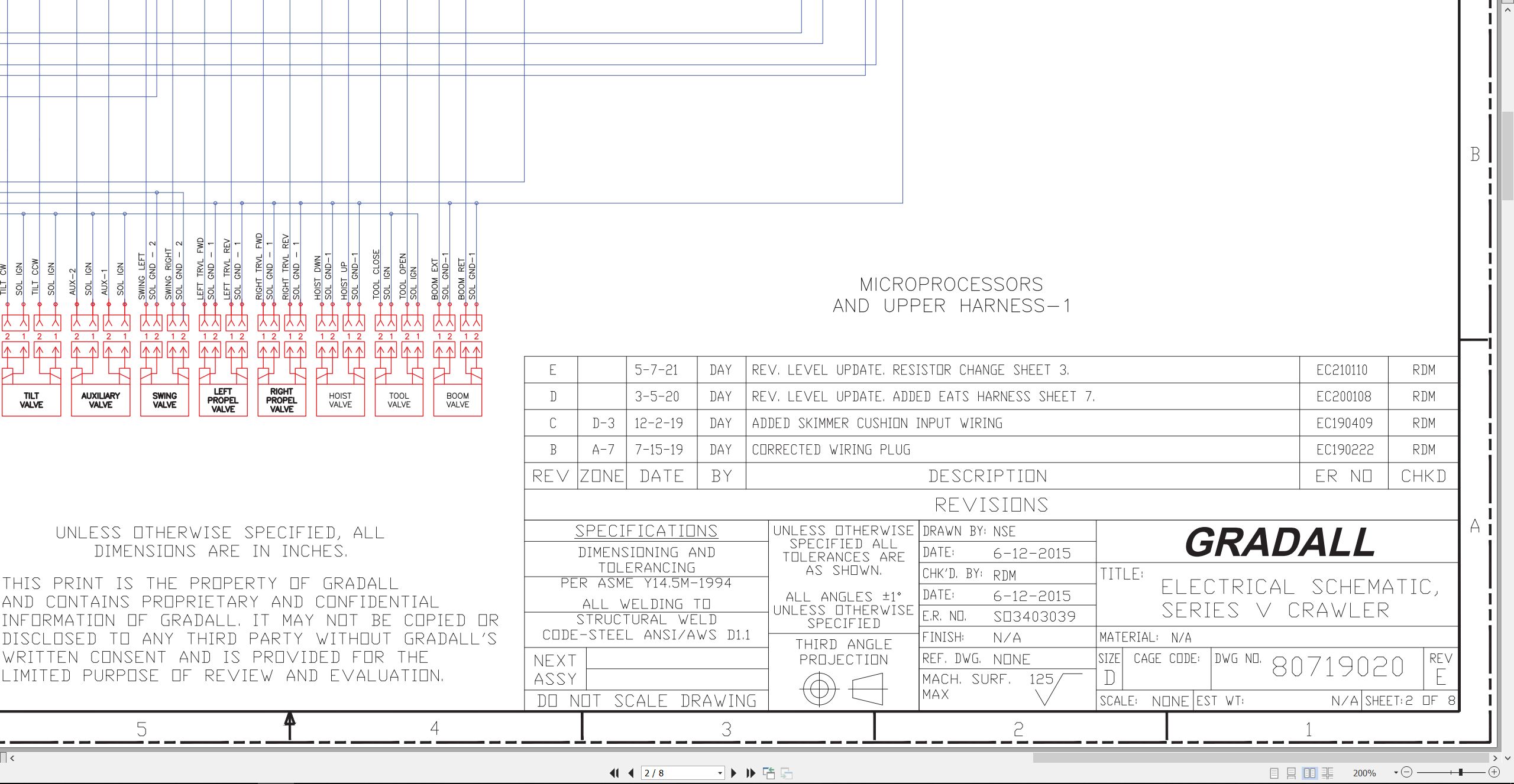
XL3200V XL3200 XL3200 to XL5210 XL5210V XL5210 XL5210V Electrical Schematic 80719020.pdf (8 Pages)
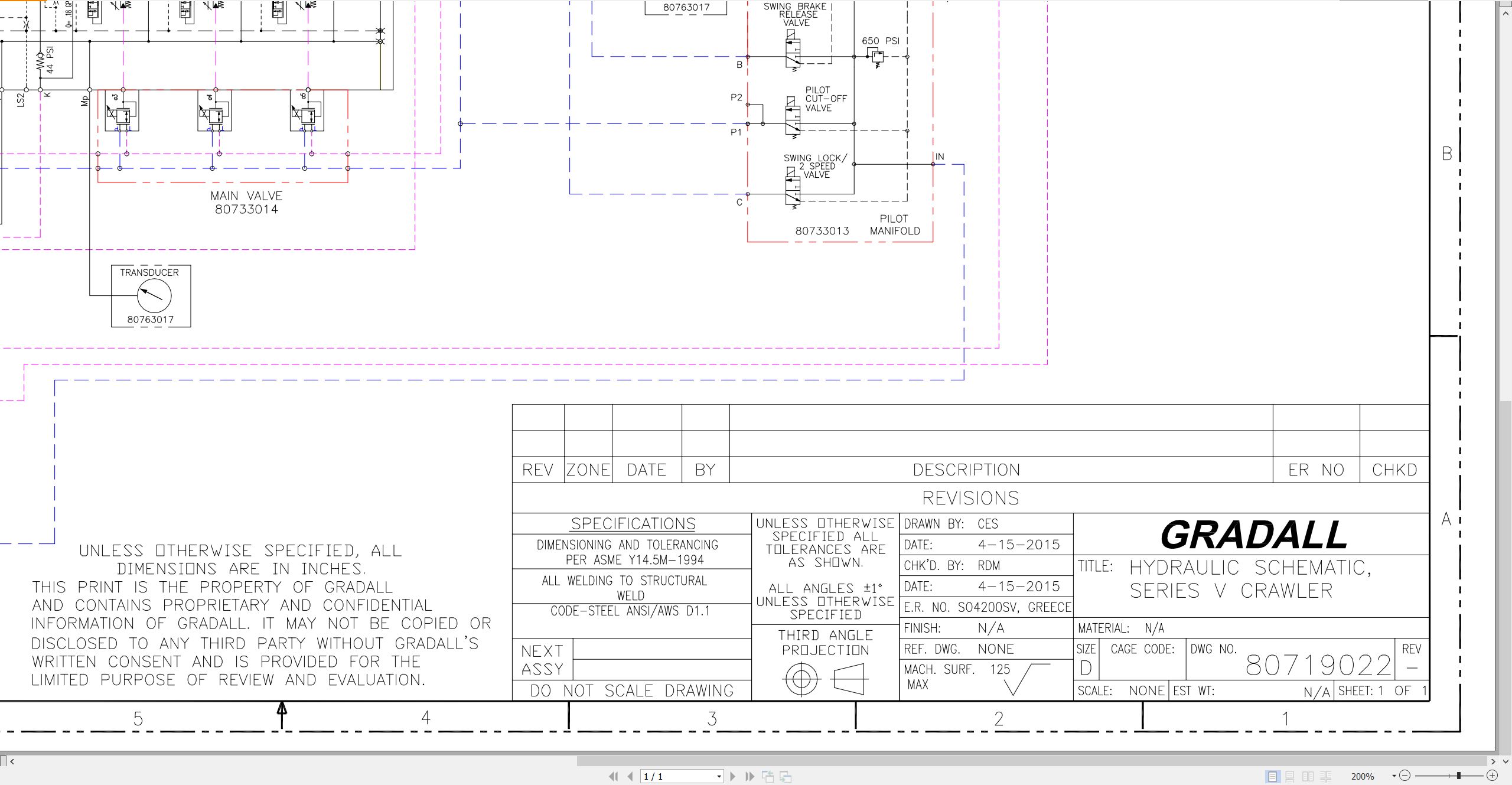
XL3200V XL3200V XL3200V to XL5210V XL5210V XL5210V Hydraulic Schematic 80719022.pdf (1 Pages)
XL3200V XL4200V XL5200V to XL5210V XL3200V Low-Profile Illustrated Parts Manual 80744006 2025.pdf (640 Pages)
Contents:
Section 1 – Frame & Attaching Parts
Frame Assembly, XL3200V & XL3210V
Frame Assembly, XL3200V Low-Profile
Frame Assembly, XL4200V, XL4210V, XL5200V & XL5210V
Upperstructure Mirror Installation
Upperstructure Mirror Installation (Steel Mirrors)
Upperstructure Covers Installation (Tier 4F Engine)
Upperstructure Covers Installation (Tier 3 Engine)
Upperstructure Covers Installation (Tier V Engine)
Valve Cover
Fuel Tank & Reservoir Installation
Fuel Tank & Reservoir Assembly (Plastic Fuel Tank)
Fuel Tank & Reservoir Assembly (Steel Fuel Tank)
Reservoir Breather Installation
Swing Bearing Installation Components
Counterweight & Swing Light Installation, XL3200V, XL3200V Low-Profile & XL3210V
Counterweight & Swing Light Installation, XL4200V, XL4210V, XL5200V & XL5210V
Counterweight Bumpers Installation, XL3200V Low-Profile, XL3210V, XL4210V & XL5210V
Boom Installation Components
Boom Installation Components, XL3200V Low-Profile
Cab Installation Components, XL3200V, XL3200V Low-Profile, XL4200V & XL5200V
Cab Installation Components, XL3210V, XL4210V & XL5210V
Section 2 – Boom
Boom Cradle, XL3200V & XL4200V
Boom Cradle, XL3200V Low-Profile
Boom Cradle, XL5200V
Boom Cradle, XL3210V, XL4210V & XL5210V
Main Boom Assembly, XL3200V & XL4200V
Main Boom Assembly, XL3200V Low-Profile
Main Boom Assembly, XL5200V
Main Boom Assembly, XL3210V, XL4210V & XL5210V
Telescope Boom Assembly, XL3200V, XL4200V & XL5200V
Telescope Boom Assembly, XL3200V Low-Profile
Telescope Boom Assembly, XL3210V, XL4210V & XL5210V
Boom Roller Assemblies
Bucket Linkage, XL3200V, XL4200V & XL5200V
Bucket Linkage, XL3200V Low-Profile
Bucket Linkage, XL3210V, XL4210V & XL5210V
Section 3 – Attachments
24†& 30†Excavating Buckets
24†& 30†Excavating Buckets (Low-Profile models only)
30†Excavating Bucket (Pin-On)
36†Excavating Buckets
42†Excavating Bucket
48†Excavating Bucket
30†& 42†High Capacity Excavating Buckets (No Teeth)
15†Trenching Bucket
18â€, 28†& 30†Pavement Removal Buckets
24†& 40†Pavement Removal Buckets
24†Ditching Bucket (No Teeth)
30†& 60†Ditching Buckets
60†Ditching Bucket w/Bolt-on Cutting Edge
66†Ditching Bucket
66†Ditching Bucket w/Bolt-on Cutting Edge
72†Ditching Bucket
72†Ditching Bucket (Pin-On)
72†& 108†Dredging Buckets
4’, 6’, 8’ & 12’ Boom Extension
Auxiliary Hydraulics, 4’, 6’, 8’ & 12’ Boom Extension
Telestick Installation, XL4200V
Telestick Installation, XL5200V
Guardrail Back Scraper
2184MM & 2800MM Conveyor Buckets (Pin-On)
8’ Grading Blade & Single Tooth Ripper
Mine Bucket
Tree Limb Shear Assembly
Fixed Thumb Grapple Assembly
Hydraulic Thumb Grapple Assembly
Single & Double Tooth Scaling Hooks
Single & Double Tooth Scaling Hooks (Pin-On)
Air Hammer (Kent 999) Installation (Pin-On), XL3210V, XL4210V & XL5210V
Hammer (Atlas SB552) Installation
Hammer (Rammer 999) Installation, (Bucket Adapter Mount)
Hammer (Rammer 999) Installation, (Pin-On)
Hammer (Rammer 999) w/Quick Switch Adapter Installation
Hammer (Rammer BR1322) w/Hammer Bracket Installation
Hammer Bracket Assembly
Section 4 – Engine & Attaching Parts
Power Unit Assembly (Tier 4F Engine)
Power Unit Assembly (Tier 3 Engine)
Power Unit Assembly (Stage V Engine)
Exhaust System Installation (Tier 4F Engine)
Exhaust System Installation (Tier 3 Engine)
Exhaust System Installation (Stage V Engine)
Air Cleaner Installation (Tier 4F Engine)
Air Cleaner Installation (Tier 3 Engine)
Air Cleaner Installation (Stage V Engine)
Air Cleaner Assembly
Cooling Unit Installation (Tier 4F Engine)
Cooling Unit Installation (Tier 3 Engine)
Cooling Unit Installation (Stage V Engine)
DEF Tank Installation (Tier 4F Engine)
DEF Tank Installation (Stage V Engine)
Gear Pump Installation
Section 5 – Drive Train
Track Chain & Shoes Assembly, XL3200V, XL3200V Low-Profile & XL3210V
Track Chain & Shoes Assembly, XL4200V, XL4210V, XL5200V & XL5210V
Track Roller
Carrier Roller
Front Idler Track Adjuster
Crawler Drive Motor Assembly – Control
Crawler Drive Motor Assembly – Hydraulic Motor
Crawler Drive Motor Assembly – Gearbox
Section 6 – Cab
Operators Cab Assembly, XL3200V, XL3200V Low-Profile, XL4200V & XL5200V
Operators Cab Assembly, XL3210V, XL4210V & XL5210V
Operators Cab, XL3200V, XL3200V Low-Profile, XL4200V & XL5200V
Operators Cab, XL3210V, XL4210V & XL5210V
Operators Cab Door, XL3200V, XL3200V Low-Profile, XL4200V & XL5200V
Operators Cab Door, XL3210V, XL4210V & XL5210V
Operators Cab Console
Pod Panel Assemblies
Operators Cab Seat Assembly
Operators Cab Seat
Pilot Cut-off Assembly
Evaporator & Heater Assembly (Pro-Air Units)
Evaporator & Heater Assembly (Victory Units)
Air Conditioning Installation
Section 7 – Controls
Foot Pedal Plate Assembly
Foot Switch (Boom Tilt) Installation (optional)
Foot Switch (Aux Hydraulics – Bidirectional Flow) Installation (optional)
Foot Switch (Aux Hydraulics – Unidirectional Flow) Installation (optional)
Radio Remote Control Installation, With Cab (optional)
Radio Remote Control Installation, Without Cab (optional)
Radio Remote Controller Installation (optional)
Remote Control Transmitter/Receiver Components (optional)
Section 8 – Hydraulic Circuits
Oil Supply to Main Pump & Control Valve
Main Valve to Pilot Manifold, XL3200V, XL3200V Low-Profile, XL4200V & XL5200V
Main Valve to Pilot Manifold, XL3210V, XL4210V & XL5210V
Dump Circuit
Hoist Cylinder Hydraulic Circuit, XL3200V, XL3210V, XL4200V, XL4210V, XL5200V, XL5210V
Hoist Cylinder Hydraulic Circuit, XL3200V Low-Profile
Boom Cylinder Hydraulic Circuit, XL3200V, XL4200V & XL5200V
Boom Cylinder Hydraulic Circuit, XL3200V Low-Profile
Boom Cylinder Hydraulic Circuit, XL3210V, XL4210V & XL5210V
Tool Cylinder Hydraulic Circuit, XL3200V, XL4200V & XL5200V
Tool Cylinder Hydraulic Circuit, XL3200V Low-Profile
Tool Cylinder Hydraulic Circuit, XL3210V, XL4210V & XL5210V
Auxiliary Hydraulic Circuit, XL3200V Low-Profile
Case Drain Circuit, XL3200V, XL4200V & XL5200V (optional)
Tilt Motor Hydraulic Circuit, XL3200V, XL3200V Low-Profile, XL4200V & XL5200V
Tilt Motor Hydraulic Circuit, XL3210V, XL4210V & XL5210V
Swing Motor Hydraulic Circuit
Upper Propelling Hydraulic Circuit
Crawler Drive Main Hydraulic Circuit
Crawler Drive Forward/Reverse Hydraulic Circuit
Section 9 – Hydraulic Components
Hoist Cylinder Assembly, XL3200V & XL3210V
Hoist Cylinder Assembly, XL3200V Low-Profile
Hoist Cylinder Assembly, XL4200V & XL4210V
Hoist Cylinder Assembly, XL5200V & XL5210V
Boom Cylinder Assembly, XL3200V & XL3210V
Boom Cylinder Assembly, XL3200V Low-Profile
Boom Cylinder Assembly, XL4200V & XL4210V
Boom Cylinder Assembly, XL5200V & XL5210V
Tool Cylinder Assembly, XL3200V
Tool Cylinder Assembly, XL3200V Low-Profile
Tool Cylinder Assembly, XL4200V & XL5200V
Tool Cylinder Assembly, XL3210V, XL4210V & XL5210V
Main Hydraulic Pump
Main Hydraulic Control Valve Assembly
Main Hydraulic Control Valve
Main Hydraulic Control Valve – End Caps
Main Hydraulic Control Valve – Valve Section, Swing
Main Hydraulic Control Valve – Valve Section, Tilt & Auxiliary
Pilot Manifold Valve Tray Hydraulic Components, XL3200V, XL3200V Low-Profile, XL4200V & XL5200V
Pilot Manifold Valve Tray Hydraulic Components, XL3210V, XL4210V & XL5210V
Pilot Manifold Assembly
Swing Transmission Assembly, XL3200V, XL3200V Low-Profile, XL4200V & XL5200V
Swing Transmission Assembly, XL3210V, XL4210V & XL5210V
Swing Motor Assembly
Swing Drive Assembly, XL3200V, XL3200V Low-Profile, XL4200V & XL5200V
Swing Drive Assembly, XL3210V, XL4210V & XL5210V
Swing Brake Assembly
Tilt Transmission Assembly, XL3200V, XL3200V Low-Profile, XL4200V & XL5200V
Tilt Transmission Assembly, XL3210V, XL4210V & XL5210V
Tilt Drive Assembly, XL3200V, XL3200V Low-Profile, XL4200V & XL5200V
Tilt Transmission, XL3210V, XL4210V & XL5210V
Tilt Motor Assembly, XL3200V, XL3200V Low-Profile, XL4200V & XL5200V
Tilt Motor Assembly, XL3210V, XL4210V & XL5210V
Tilt Brake Assembly, XL3200V, XL3200V Low-Profile, XL4200V & XL5200V
Tilt Brake Assembly, XL3210V, XL4210V & XL5210V
Center Pin Assembly
Section 10 – Electrical
Electrical Components
Battery Installation
Service Panel Assembly
Cab Console Circuit Board
Section 11 – Decals
Decals Installation, XL3200V, XL3200V Low-Profile, XL4200V & XL5200V
Decals Installation, XL3210V, XL4210V & XL5210V
Section 12 – Options
Air Hammer (Kent 999) Supply Plumbing Installation, XL3210V, XL4210V & XL5210V
Air Hammer (Kent 999) Air Line Oiler Installation, XL3210V, XL4210V & XL5210V
Attachment Case Drain Installation, XL3210V
Auxiliary Hydraulic Plumbing Installation, XL3200V, XL4200V & XL5200V
Auxiliary Hydraulic Plumbing Installation, XL3210V, XL4210V & XL5210V
Auxiliary Oil to Air Conversion Installation, XL3210V, XL4210V & XL5210V
Auxiliary Tube Adapter Installation
Belly Pan Installation, XL3210V, XL4210V & XL5210V
Bolt-On Lifting Yoke Installation, XL3210V, XL4210V & XL5210V
Bolt-On Folding Lifting Yoke Installation, XL3210V, XL4210V & XL5210V
Bolt-On Crawler Step Installation, XL4200V, XL4210V, XL5200V & XL5210V
Boom Hole Covers (main boom) Installation, XL3210V, XL4210V & XL5210V
Boom Hole Covers (telescope boom) Installation, XL5210V
Boom Top Guard Installation, XL3210V, XL4210V & XL5210V
Cab Air Filter Installation, XL3200V, XL4200V & XL5200V
Cab Air Filter Installation, XL3210V, XL4210V & XL5210V
Cab Guard Installation (ROPS Certified)
Cab Guard Installation (non – ROPS Certified)
Cab Roof Guard (mount to cab lugs) Installations, XL3200V, XL4200V & XL5200V
Cab Roof Guard Installation (solid peaked)
Cab Roof Guard Installation (bars)
Cab Roof Guard Installation (mesh)
Camera Kit Installation
Camera (Split-Screen) Kit Installation
Crawler Skid Plate Installation
Engine Block Heater Installation (110v)
Escape Hammer Installation
Fire Extinguisher Installation, XL3200V, XL4200V & XL5200V
Fire Extinguisher Installation (front of cab), XL3200V, XL4200V & XL5200V
Fire Extinguisher Installation, XL3210V, XL4210V & XL5210V
Fire Supression System Installation
Front Cab Guard (bottom) Installation (solid)
Front Cab Guard (bottom) Installation (slotted)
Front Window Guard Installation (solid bars)
Front Window Guard Installation (mesh)
Front Window Guard Installation (hinged wire mesh)
Front Window (Heat Resistant) Installation
Hand Rail Installation
Hoist Lock Installation
Hoist Stop Installation
Hydraulic Fluid Installation, Quintolubric 888-68
Hydraulic Fluid Installation, Ecosafe FR-68
Hydraulic Fluid Installation, Ecosafe FR-46
Hydraulic Supressor Installation
Lock Pin Installation
Low Pressure Aux Return Installation
Roller Bracket Guards Installation, XL3210V, XL4210V & XL5210V
Seat Belt Installations
Seat Belt Installation, 3-Point
Strobe Light (LED) Installation
Strobe Light (LED) Installation, XL3200V, XL4200V & XL5200V
Strobe Light (counterweight-mounted) Installation
Strobe Light Branch Guard Installation, XL3200V, XL4200V & XL5200V
Sun Visor Installation
Swing Motor Port Jumper Circuit Installation
Tool Open Lock Installation
Two-Point Lift Ring Installation
Vandal Covers Installation, XL3200V, XL4200V & XL5200V
Window Guard Installation, XL3200V, XL4200V & XL5200V
Work Light Installation
Work Light (LED) Installation
Work Light Guards Installation
Work Light (Hi-Temp) Installation, XL3210V, XL4210V & XL5210V
Work Light (Hi-Temp) Installation, XL3210V, XL4210V & XL5210V Remote Control – (No Cab)
Zone Lights (Red Stripe LED) Installation
Recommended Spare Parts
Part Number Index
XL3200V XL4200V XL5200V XL3210V to XL3200V Low-Profile Operator Safety Manual 80744007 2026.pdf (134 Pages)
Contents:
Section 1 – General Safety Practices
1.1 Hazard Classification System
1.2 General Precautions
1.3 Operation Safety
1.4 Personal Protection Equipment
Section 2 – Pre-Operation and Controls
2.1 Pre-Operation Checks & Inspection
2.2 Walk-Around Inspection
2.3 Safety Decals – XL3200V, XL4200V & XL5200V
2.4 Safety Decals – XL3210V, XL4210V & XL5210V
2.5 Cab Components
2.6 Cab Controls & Indicators
2.7 Radio Control Electrical Panel (No Cab; optional)
2.8 Radio Control Strobe Lights
Section 3 – Operation
3.1 Engine Operation
3.2 Checks Before Operation
3.3 Crawler Chassis
3.4 Typical Dig Cycle
3.5 Lifting & Placing a Load – XL3200V, XL4200V & XL5200V
3.6 Lift Capacity – XL3200V, XL4200V & XL5200V
3.7 Engine Shutdown
3.8 Parking the Excavator
3.9 Preservation & Storage
3.10 Radio Control Activation (optional)
3.11 Parked Regeneration (Stage V Engines)
Section 4 – Attachments
4.1 Approved Attachments
4.2 Unapproved Attachments
4.3 Attachment Operation
4.4 Adapter Attachment Installation
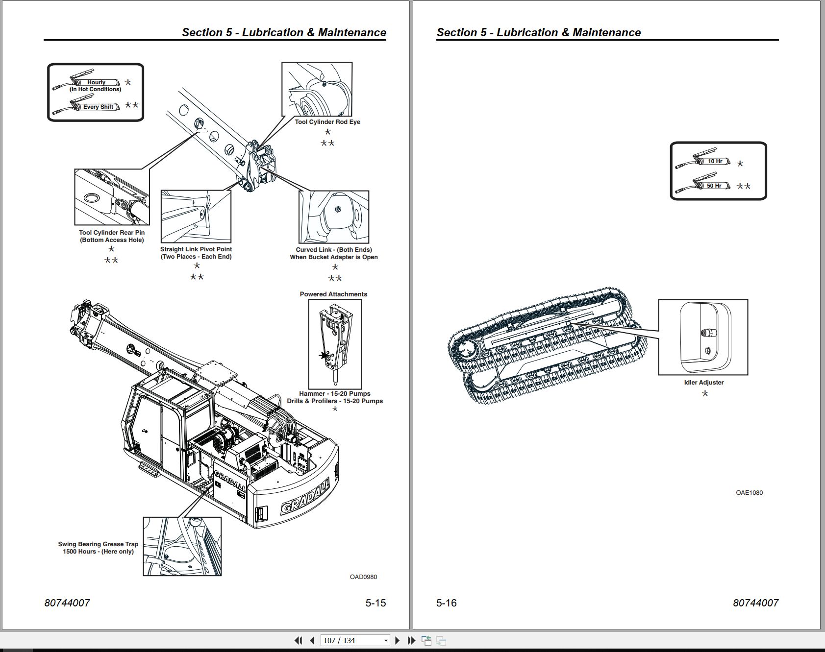
Section 5 – Lubrication & Maintenance
5.1 Introduction
5.2 General Maintenance Instructions
5.3 Service & Maintenance Schedules
5.4 Lubrication Schedules
5.5 Boom Adjustments & Maintenance
Section 6 – Emergency Procedures
6.1 Loss Of Power
6.2 If You Get Stuck
Section 7 – Specifications
7.1 Product Specifications
7.2 Torque Chart
7.3 Fuses
Pre-Operation Inspection Checklist
Index
XL3200V XL4200V XL5200V XL3210V to XL3200V Low-Profile Service Supplement 80744008 2026.pdf (250 Pages)
Contents:
Section 1 – General Safety Practices
Section 2 – Pre-Operation and Controls
Section 3 – Operation
Section 4 – Attachments
Section 5 – Lubrication & Maintenance
Section 6 – Emergency Procedures
Section 7 – Specifications
Pre-Operation Inspection Checklist
Index
ELECTRICAL
41200184_D_Bodas System Training_3-5-2026.pdf
Slide 1: BODAS Use & Operation Guide
Slide 2: BODAS – Program Notes
Slide 3: Program Notes (Continued)
Slide 4: Processor & Software
Slide 5: BODAS Software
Slide 6: Serial Communications Cable
Slide 7: This Doesn’t Work!
Slide 8: CAN Communication Port
Slide 9: Program Setup
Slide 10: Program Setup (Continued)
Slide 11: Program Setup (Continued)
Slide 12: Program Setup (Continued)
Slide 13
Slide 14: Using Bodas
Slide 15: Using Bodas (Continued)
Slide 16: Using Bodas (Continued)
Slide 17: Using Bodas (Continued)
Slide 18: Using Bodas (Continued)
Slide 19
Slide 20: Bodas Menus
Slide 21
Slide 22: Parameter-Calibration
Slide 23: Parameter-Calibration
Slide 24: Parameter-Calibration
Slide 25: Parameter-Calibration Expanded
Slide 26: Parameter-Calibrations
Slide 27: Parameter-Calibrations
Slide 28: Parameter- Machine and Truck type
Slide 29: Parameter- Unlocking
Slide 30: Parameter- Unlocked Parameters
Slide 31: Parameter- Unlocked Parameters
Slide 32: Parameter Settings
Slide 33: Parameter Menus Expanded
Slide 34: Parameter Menus Expanded
Slide 35: Parameter Menus Expanded
Slide 36: Parameter Menus Expanded
Slide 37: Parameter Menu Details
Slide 38: Parameter Menus Detail & Adjustments
Slide 39: Parameter Menus Detail & Adjustments
Slide 40
Slide 41: Error Messages
Slide 42: Error Messages (Continued)
Slide 43: Error Messages (Continued)
Slide 44
Slide 45: Processdata Menu
Slide 46: Processdata Menu (Continued)
Slide 47: Processdata Menu (Continued)
Slide 48: Processdata Menu (Continued)
Slide 49: Processdata Menu (Continued)
Slide 50: Processdata Menu (Continued)
Slide 51: Processdata Menu (Continued)
Slide 52: Processdata Menu (Continued)
Slide 53
Slide 54: How to Graph
Slide 55: Saving a Parfile
Slide 56: WARNING! WHAT NOT TO DO!
Slide 57
80719020 (E) Electrical Schematic
80763138 (A) Console Circuit Board
80763158 (H) Upper Harness
80763156 (B) Cab Harness
HYDRAULIC
80719022 (-) Hydraulic Schematic
CRAWLER
XL-Series Crawler Maintenance Manual
Introduction
Nomenclature
Track Adjustment
Shoe Contact with Rock Guard
Crawler Travel Speed
Crawler Tracking
Track Chain
Track Rollers
Idler Roller with Track Tension and Adjuster Components
Driver Sprocket
Miscellaneous
XL3200V XL4200V XL5200V XL3210V XL4210V XL5210V Operator Safety Manual 8500-4010 2016 FR.pdf (112 Pages)
Contents:
Journal de révision
À lire en premier
Table des matières
Section 1 РPratiques de s̩curit̩ g̩n̩rales
1.1 Système de classification des dangers
Système de mise en garde et termes de sécurité
1.2 Précautions générales
1.3 Sécurité d’utilisation
Risques électriques
Risques relatifs au pivotement
Risque de glissade et de chute
Risques d’écrasement
Risques relatifs au déplacement
Risque de basculement
Risques relatifs aux produits chimiques
Risque relatif à la poussière
1.4 Équipement de protection personnelle
Section 2 – Avant la mise en service et commandes
2.1 Vérifications et inspection avant la mise en service
2.2 Tour d’inspection
2.3 Autocollants de s̩curit̩ РXL3200V, XL4200V et XL5200V
Emplacements des autocollants
2.4 Composants de la cabine
2.5 Commandes et témoins de la cabine
Moniteur électronique
Affichage numérique du moniteur électronique
Accoudoir droit
Accoudoir gauche
Sélection de configuration des leviers de commande
Leviers de commande
Réglages du siège de l’opérateur
Allumage
Essuie-glace intermittent/lave-glace
Section 3 – Fonctionnement
3.1 Fonctionnement du moteur
Démarrage du moteur
Fonctionnement normal du moteur
Dispositifs d’aide au démarrage par temps froid
3.2 Vérifications avant l’utilisation
3.3 Bâti de l’unité à chenilles
Pédales/leviers d’entraînement des chenilles
Utilisation correcte de l’unité à chenilles
Fonctionnement de l’unité à chenilles
3.4 Cycle de creusement typique
Fonctions SAE standard de la flèche et de l’accessoire
3.5 Levage et positionnement d’une charge – XL3200V, XL4200V et XL5200V
Précautions
Généralités
Positionnement de la machine pour un levage
Planification d’un levage
Transport d’une charge
Livraison d’une charge
3.6 Capacit̩ de levage РXL3200V, XL4200V et XL5200V
3.7 Arrêt du moteur
3.8 Stationnement de l’excavatrice
Précaution
Procédure de stationnement
3.9 Préservation et entreposage
Entretien
Section 4 – Accessoires
4.1 Accessoires agréés
4.2 Accessoires non agréés
4.3 Fonctionnement de l’accessoire
Godets excavateurs
Godets de creusement de fossés
Godets de creusement de tranchées
Godet de destruction de la chaussée
Godet de dragage
Lame niveleuse
4.4 Installation de l’accessoire adaptateur
Section 5 – Lubrification et entretien
5.1 Introduction
Vêtements et équipements de protection
5.2 Instructions d’entretien général
5.3 Programmes d’entretien
Programme d’entretien des 10 heures
Programme d’entretien des 50 heures
Programme d’entretien des 100 heures
Programme d’entretien des 30 premiers jours (250 h max.) et des 250 heures
Programme d’entretien des 600 heures
Programme d’entretien des 750 heures
Programme d’entretien des 1500 heures
5.4 Programmes de lubrification
XL3200V, XL4200V et XL5200V
Section 6 – Procédures d’urgence
6.1 Perte de puissance
6.2 En cas d’enlisement
Section 7 РCaract̩ristiques
7.1 Caractéristiques du produit
Contenances en lubrifiant et en liquides
Batterie
7.2 Tableau des couples de serrage
7.3 Fusibles
Liste de contrôle d’inspection des excavateurs
Index

REALEASE :
REALEASE :

REALEASE :
REALEASE :

REALEASE :
REALEASE :

REALEASE :
REALEASE :

REALEASE :
REALEASE :

REALEASE :
REALEASE :

REALEASE :
REALEASE :

REALEASE :
REALEASE :
 Automotive - Heavy Equipment - Truck & Bus - Forklift - Crane