
17 ITEMSVIEW CART


Total: 970.00
Expert Support
Full Speed
100% Working
30 USD
List of Files:
XL4310II Owner Operators Manual 8043-4286 2007.pdf (66 Pages)
XL4310II Combined Service Manual 8043-4287 2007.pdf (640 Pages)
Contents:
8043-4287 XL4310 II Combined Service Manual
OPERATOR INSTRUCTION
8043-4286 XL4310 II Owner/Operator Manual
HYDRAULIC SYSTEM OPERATION
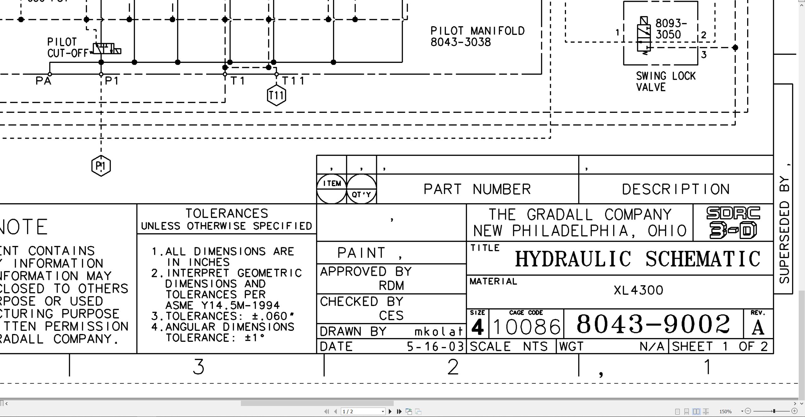
8043-9002 Hydraulic Schematic
XL4310II Start-Up Procedure
RA64-555 Rexroth Joystick
RA10097-S Rexroth Gear Pump Service Instructions
HYDRAULIC TEST & ADJUSTMENT
8043-9016 Final Test Report
MECHANICAL ADJUSTMENTS
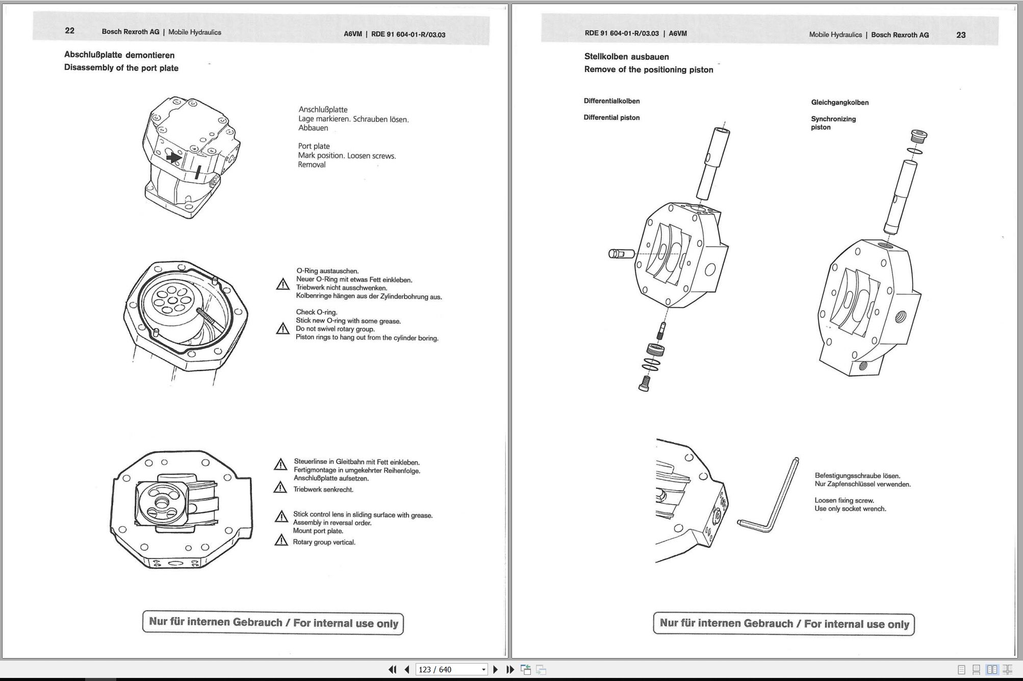
RDE91604-01-R Rexroth Drive Motor Repair
79657 Ausco Brake Technical Page
RDE91001-03-R Rexroth Swing/Tilt Motor Repair
ELECTRICAL
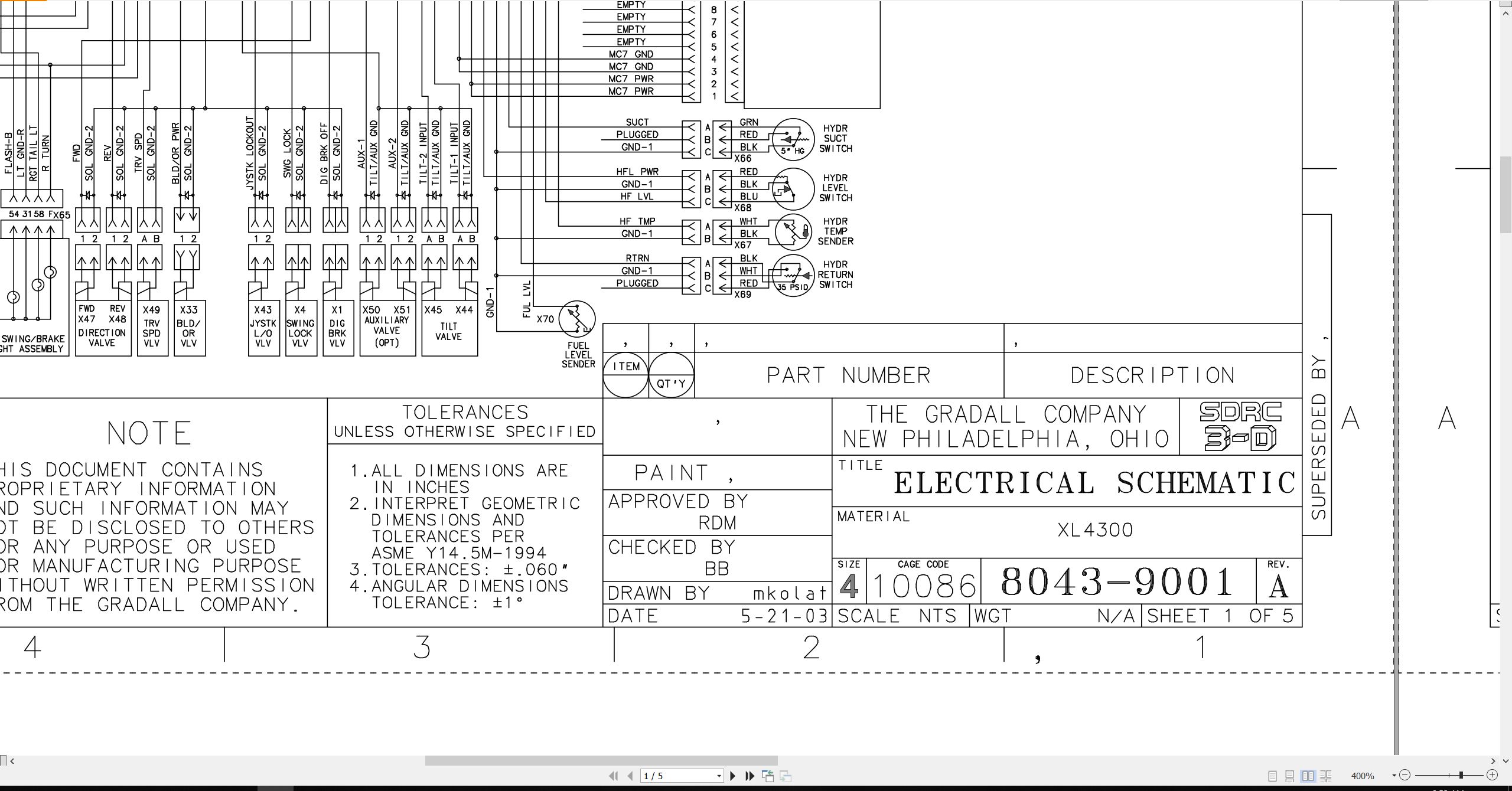
8043-9001 Electrical Schematic
1M-128 Delco Remy 28-MT Cranking Motor Service Manual
8046-3004 Upper Harness
8046-3113 Engine Harness
8046-3003 Cab Harness
8046-5002 Console Wiring
8046-3036 E.M.U
8046-3008 V.E.C
8046-3012 Relay Box
8046-3013 V.E.C/PWR Ground Harness
DRIVE AXLE
AP(L)-B 765/775 ZF Front Axle Service Manual
2 HL 100 ZF-Transmission Service Manual
2 HL 100 ZF-Transmission Operation Manual
WHEEL & RIM
0009 Rim & Wheel Safety Manual
MISCELLANEOUS
20013 Gradall Safety Manual
HE92-2 EMI Safety Manual – 8060-3007.pdf
8060-9016 Hydraulic Fitting Torque Chart
XL4310II Illustrated Parts Manual 80434285 2025.pdf (332 Pages)
Contents:
Service Kits
Section 1 Frame & Attaching Parts
Figure 1-1 Frame & Attaching Parts
Figure 1-2 Rotating Platform
Figure 1-3 Swing Bearing, Cradle & Hoist Cylinder Mounting & Lube System
Figure 1-4 Frame & Plumbing
Section 2 Boom
Figure 2-1 Boom Cradle
Figure 2-2 Main Boom Assembly & Rollers
Figure 2-3 Telescope Boom Assembly
Figure 2-4 Roller Assemblies
Figure 2-5 Bucket Linkage
Section 3 Attachments
Figure 3-1 Scaling Hook Installation
Section 4 Engine & Attaching Parts
Figure 4-1 Power Unit Assembly, L.H. View
Figure 4-2 Power Unit Assembly, R.H. View
Figure 4-3 Deere Engine
Figure 4-4 Air Cleaner & Installation
Figure 4-5 Air Cleaner
Figure 4-6 Exhaust System
Figure 4-7 Fuel Tank Assembly
Figure 4-8 Oil Cooler, Radiator & Hoses
Section 5 Drive Train
Figure 5-1 Transmission – Input Housing
Figure 5-2 Transmission – Input
Figure 5-3 Transmission – Housing
Figure 5-4 Transmission – Oil Pipe
Figure 5-5 Transmission – Coupling
Figure 5-6 Transmission – Disc Brake
Figure 5-7 Transmission – Planetary Drive
Figure 5-8 Transmission – Disconnection
Figure 5-9 Transmission – Spurred Gear Drive
Figure 5-10 Transmission – Shift Sensor
Figure 5-11 Transmission – Output
Figure 5-12 Steer Axle – Axle Housing
Figure 5-13 Steer Axle – Differential Spider, Cage & Nest
Figure 5-14 Steer Axle – Differential Carrier
Figure 5-15 Steer Axle – Wheel End
Figure 5-16 Steer Axle – Gearbox & Brake
Figure 5-17 Steer Axle – Steering Gear
Figure 5-18 Drive Axle – Axle Housing
Figure 5-19 Drive Axle – Differential
Figure 5-20 Drive Axle – Hub Carrier & Wheel End
Figure 5-21 Drive Axle – Gearbox & Brake
Section 6 Cab
Figure 6-1 Operators Cab
Figure 6-2 Cab Door
Figure 6-3 Cab Interior Components
Figure 6-4 Cab Console
Figure 6-5 Cab Seat
Figure 6-6 Cab Heater & Installation
Figure 6-7 Wiper-Washer Installation Components
Figure 6-8 Pilot Cut-off Assembly
Section 7 Controls
Figure 7-1 Joystick
Figure 7-2 Steering Column, Foot Pedals & Installation
Section 8 Hydraulic Circuits
Figure 8-1 Oil Supply to Pumps
Figure 8-2 Hydraulic Pressure to Control Valves
Figure 8-3 Main Valve to Pilot Manifold Hydraulic Hosing
Figure 8-4 Dump Circuit
Figure 8-5 Hydraulic Hosing to Joysticks & Propel
Figure 8-6 Hoist Pilot
Figure 8-7 Boom Pilot
Figure 8-8 Tool Pilot
Figure 8-9 Swing & Swing Brake Pilot
Figure 8-10 Hoist Cylinder
Figure 8-11 Hoist Tubes Replacement Kit
Figure 8-12 Boom Cylinder
Figure 8-13 Tool Cylinder
Figure 8-14 Swing Motor
Figure 8-15 Swing Tubes Replacement Kit
Figure 8-16 Tilt Motor
Figure 8-17 Upper Propelling
Figure 8-18 Chassis Supply
Figure 8-19 Chassis Supply Pilot
Figure 8-20 Tilt Pilot
Section 9 Hydraulic Components
Figure 9-1 Hoist Cylinder Assembly
Figure 9-2 Boom Cylinder Assembly
Figure 9-3 Tool Cylinder Assembly
Figure 9-4 Oscillation Cylinder Assembly
Figure 9-5 Swing Lock Cylinder
Figure 9-6 Main Pump
Figure 9-7 Pilot Manifold Valve Tray
Figure 9-8 Pilot Manifold
Figure 9-9 Main Hydraulic Control Valve Assembly
Figure 9-10 Main Hydraulic Control Valve
Figure 9-11 Main Hydraulic Control Valve – Spools & End Caps
Figure 9-12 Main Hydraulic Control Valve – Swing Section
Figure 9-13 Main Hydraulic Control Valve – Seal Kits
Figure 9-14 Cold Start Valve
Figure 9-15 Reservoir Assembly
Figure 9-16 Swing Transmission Assembly
Figure 9-17 Swing Drive Assembly
Figure 9-18 Swing Motor
Figure 9-19 Swing Brake
Figure 9-20 Tilt Transmission Assembly
Figure 9-21 Tilt Transmission
Figure 9-22 Tilt Motor
Figure 9-23 Tilt Brake
Figure 9-24 Drive Motor
Figure 9-25 Center Pin Assembly
Figure 9-26 Gear Pump
Figure 9-27 Foot Operated Pedal Valve
Figure 9-28 Transmission Control Valve Assembly
Figure 9-29 Transmission Control Valve Installation
Figure 9-30 Six Way Diverter Valve
Figure 9-31 Steering Control
Figure 9-32 Oscillation/Cylinder Anti-Drift Valve
Figure 9-33 Swing Reduction Valve
Section 10 Electrical
Figure 10-1 Batteries, VEC & Miscellaneous Components
Figure 10-2 Cab Console
Section 11 Decals
Figure 11-1 Decals, Manuals & Boom Tie Down
Section 12 Options
Figure 12-1 Air Conditioner Installation Components
Figure 12-2 Air Conditioning Evaporator Kit
Figure 12-3 Cab Roof and Window Guard Installation
Figure 12-4 Blade Cylinder Assembly
Figure 12-5 Blade Selector Valve Assembly
Figure 12-6 Chassis Mounted Blade Installation Components
Figure 12-7 HID Light Installation
Figure 12-8 Fire Supression System
Figure 12-9 Engine Shutdown Installation Components
Figure 12-10 Pressurized Cab Fan Installation
Recommended Spare Parts
Part Number Index
XL4300II XL4310II Electrical Schematic 80439001.pdf (5 Pages)
XL4300II XL4310II Hydraulic Schematic 80439002.pdf (2 Pages)

REALEASE :
REALEASE :

REALEASE :
REALEASE :

REALEASE :
REALEASE :

REALEASE :
REALEASE :

REALEASE :
REALEASE :

REALEASE :
REALEASE :

REALEASE :
REALEASE :

REALEASE :
REALEASE :
 Automotive - Heavy Equipment - Truck & Bus - Forklift - Crane