
7 ITEMSVIEW CART


Total: 405.00
Expert Support
Full Speed
100% Working
30 USD
List of Files:
XL3300 XL4300 XL5300 to XL5310 XL4320 Series III V Rough Terrain Chassis Lube Chart 80644009.pdf (1 Pages)
XL4340V Skimmer Boom Illustrated Parts Manual 80644010 2025.pdf (372 Pages)
Contents:
Section 1 – Frame & Attaching Parts
Frame & Cover Plate Installation
Tool Boxes & Steps Installation
Skid Plate Installation
Upperstructure Mirror Installation
Upperstructure Mirror Installation (Steel Mirrors)
Upperstructure Covers Installation
Valve Cover
Fuel Tank & Reservoir Installation
Fuel Tank & Reservoir Assembly (Steel Fuel Tank)
Reservoir Breather Installation
Swing Bearing Installation Components
Swing Lock Installation
Counterweight & Swing Light Installation
Cab Installation Components
Center Pin Installation
Section 2 – Boom
Boom Installation
First Boom Assembly
Second Boom Assembly
Third Boom Assembly
Skimmer Guards Installation
Winch & Cables Components Installation
Hydraulic Cable Winch Assembly
Section 3 – Attachments
Skimmer Tool Installation
Section 4 – Engine & Attaching Parts
Power Unit Assembly
Exhaust System Installation
Air Cleaner Installation
Air Cleaner Assembly
Cooling Unit Installation
DEF Tank Installation
Gear Pump Installation
Section 5 – Drive Train
Transmission, Drive Motor and Drive Shafts Installation
Axle Installation
Tire & Wheel Assembly
Transmission – Input Housing
Transmission – Housing
Transmission – Disc Brake
Transmission – Coupling
Transmission – Planetary Drive
Transmission – Output
Transmission – Shift Sensor
Transmission – Oil Pipe
Steer Axle – Input
Steer Axle – Differential
Steer Axle – Axle Casing
Steer Axle – Joint Housing
Steer Axle – Steering Cylinder
Steer Axle – Output
Rigid Axle – Input
Rigid Axle – Differential
Rigid Axle – Axle Casing
Rigid Axle – Hub Carrier
Rigid Axle – Output
Section 6 – Cab
Operators Cab Assembly
Operators Cab
Operators Cab Door
Operators Cab Console
Pod Panel Assemblies
Operators Cab Seat Assembly
Operators Cab Seat
Pilot Cut-off Assembly
Evaporator & Heater Assembly (Pro-Air Units)
Evaporator & Heater Assembly (Victory Units)
Air Conditioning Installation
Section 7 – Controls
Foot Pedal Plate Assembly
Section 8 – Hydraulic Circuits
Oil Supply to Main Pump & Control Valve
Hoist Cylinder (Front of Boom) Hydraulic Circuit
Hoist Cylinder (Rear of Boom) Hydraulic Circuit
Main Valve to Cable Winch Circuit
Cable Tensioner Circuit
Main Valve to Pilot Manifold
Main Valve to Tilt Control Valve
Dump Circuit
Swing Motor Hydraulic Circuit
Upper Propelling Hydraulic Circuit
Chassis Supply Hydraulic Circuit
Steering Control and Brake Pedal Valve Hydraulic Circuit
Oscillation Circuit
Outrigger & Blade Circuit
Steering & Brake Circuit
Drive Motor & Transmission Circuit
Section 9 – Hydraulic Components
Hoist Cylinder Assembly (Front of Boom)
Hoist Cylinder Assembly, (Rear of Boom)
Drive Motor
Main Hydraulic Pump
Main Hydraulic Control Valve Assembly
Main Hydraulic Control Valve
Main Hydraulic Control Valve – End Caps
Main Hydraulic Control Valve – Valve Section, Swing
Main Hydraulic Control Valve – Valve Section, Chassis Supply & Auxiliary
Pilot Manifold Valve Tray Hydraulic Components
Pilot Manifold Assembly
Swing Transmission Assembly
Swing Motor Assembly
Swing Drive Assembly
Swing Brake Assembly
Center Pin Assembly
Center Pin
Steering Control Unit
Transmission Control Valve Assembly
Rear Outrigger Valve Assembly
Front Outrigger Valve Assembly
Outrigger Selector Valve
Oscillation Lock Valve Assembly
Oscillation Lock Valve
Section 10 – Electrical
Electrical Components
Electrical Components (Skimmer Boom)
Battery Installation
Service Panel Assembly
Cab Console Circuit Board
Undercarriage Harness Installation
Work Lights Installation
Main Control Valve Jumper Harnesses
Section 11 – Decals
Decals Installation
Section 12 – Options
Blade Installation
Cab Air Filter Installation
Cab Guard Installation (non – ROPS Certified)
Cab Roof Guard Installation (bars)
Camera Kit Installation
Dual Beacon (LED) Installation
Emergency Hydraulics Installation
Engine Block Heater Installation (110v)
Fire Extinguisher Installation
Front Cab Guard (bottom) Installation (solid)
Front Window (Heat Resistant) Installation
Hydraulic Fluid Installation, Quintolubric 888-68
Lexan Glass Installation (R.H. Cab Window)
Power Supply (12-volt) Installation
Tire Shield Installation
Recommended Spare Parts
Part Number Index
XL4340V Skimmer Boom Operator Safety Manual 80644011 2023.pdf (86 Pages)
Contents:
Section 1 – General Safety Practices
1.1 Hazard Classification System
Safety Alert System and Safety Signal Words
1.2 General Precautions
1.3 Operation Safety
Electrical Hazards
Swing Hazards
Slip and Fall Hazard
Crush Hazards
Travel Hazards
Tip Over Hazard
Chemical Hazards
Dust Hazard
1.4 Personal Protection Equipment
Section 2 – Pre-Operation and Controls
2.1 Pre-Operation Checks & Inspection
2.2 Walk-Around Inspection
2.3 Safety Decals
Decal Locations
2.4 Cab Components
2.5 Cab Controls & Indicators
Electronic Monitoring Unit
Electronic Monitoring Unit Digital Display
Right Hand Arm Pod
Left Hand Arm Pod
Joystick Controls
Operator Seat Adjustments
Ignition
Park Brake Switch
Section 3 – Operation
3.1 Engine Operation
Starting Engine
Normal Engine Operation
Cold Weather Starting Aids
3.2 Checks Before Operation
3.3 Brake System
3.4 Travel Modes
Moving Machine Less than 4.6m (5 yds)
Over-the-Road Travel
3.5 Engine Shutdown
3.6 Parking the Excavator
Precaution
Parking Procedure
3.7 Preservation & Storage
Maintenance
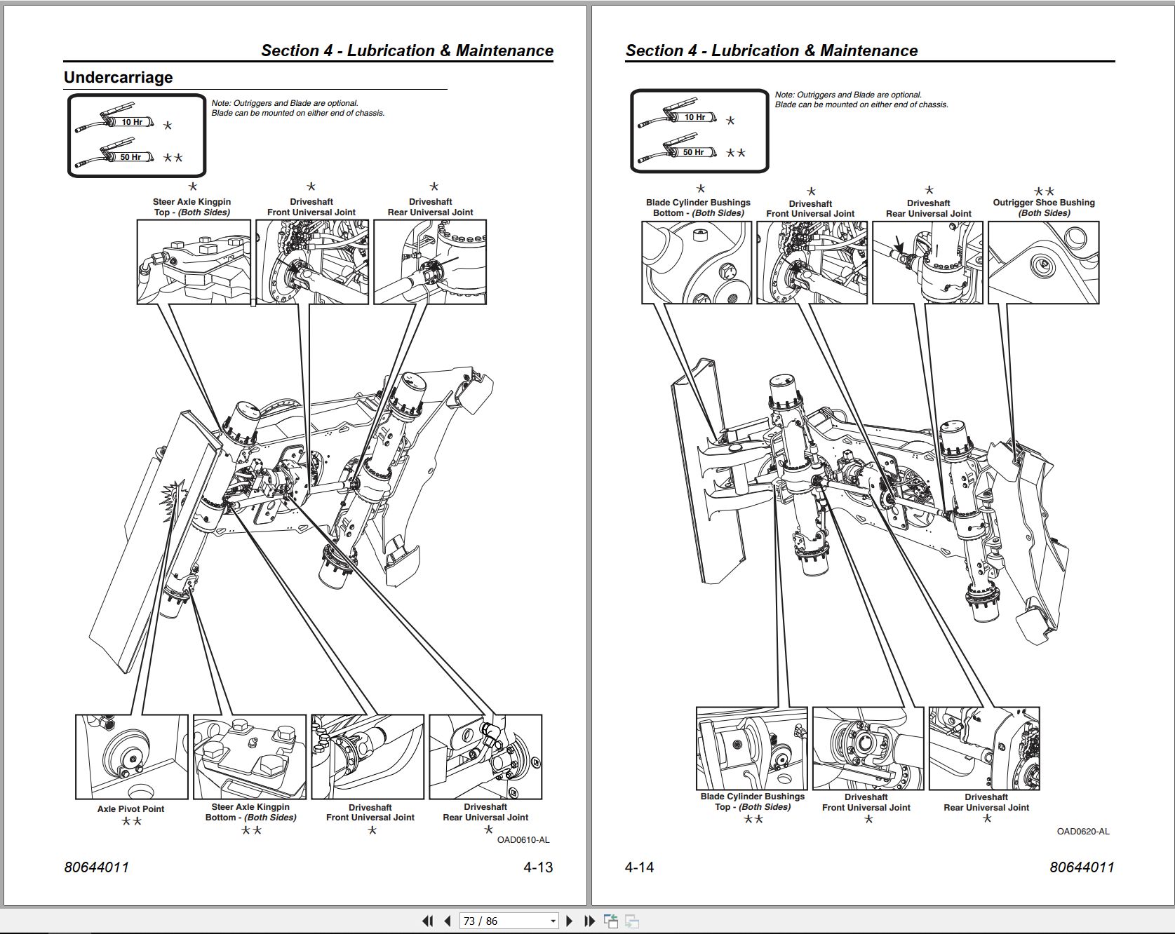
Section 4 – Lubrication & Maintenance
4.1 Introduction
Clothing and Safety Gear
4.2 General Maintenance Instructions
Tire Service
4.3 Service & Maintenance Schedules
10 Hour Maintenance Schedule
50 Hour Maintenance Schedule
100 Hour Maintenance Schedule
1st 30 Days (250 hrs Max) & 250 Hour Maintenance Schedule
500 Hour Maintenance Schedule
750 Hour Maintenance Schedule
1500 Hour Maintenance Schedule
4.4 Lubrication Schedules
Boom Sheaves
Boom Rollers
Hoist Cylinders & Swing Bearing
Undercarriage
Section 5 – Emergency Procedures
5.1 Loss Of Power
5.2 Towing the machine
Section 6 – Specifications
6.1 Product Specifications
Lubrication & Fluid Capacities
Tires
Battery
6.2 Torque Chart
6.3 Fuses
Index
XL4340V Skimmer Boom Service Supplement 80644012 2023.pdf (541 Pages)
Contents:
Section 1 – General Safety Practices
Section 2 – Pre-Operation and Controls
Section 3 – Operation
Section 4 – Lubrication & Maintenance
Section 5 – Emergency Procedures
Section 6 – Specifications
Index
ELECTRICAL
BODAS System Training
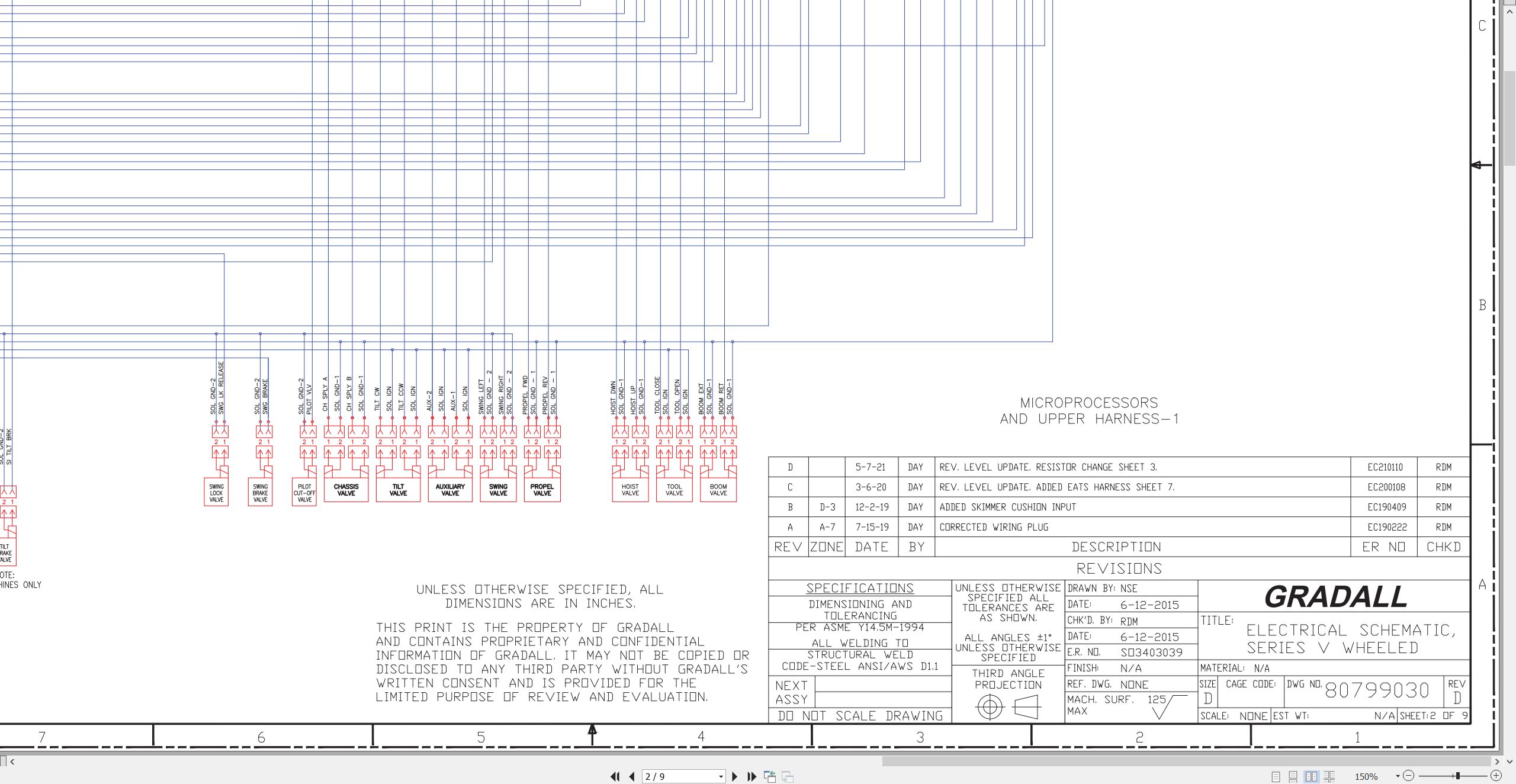
80799030 Electrical Schematic
80763138 Console Circuit Board
80763135 Upper Harness
80763136 Cab Harness
80723076 Skimmer Boom Cushion Harness (S/N 4310000015)
80723079 Skimmer Boom Cushion Harness (S/N 4340000101 & After)
HYDRAULIC
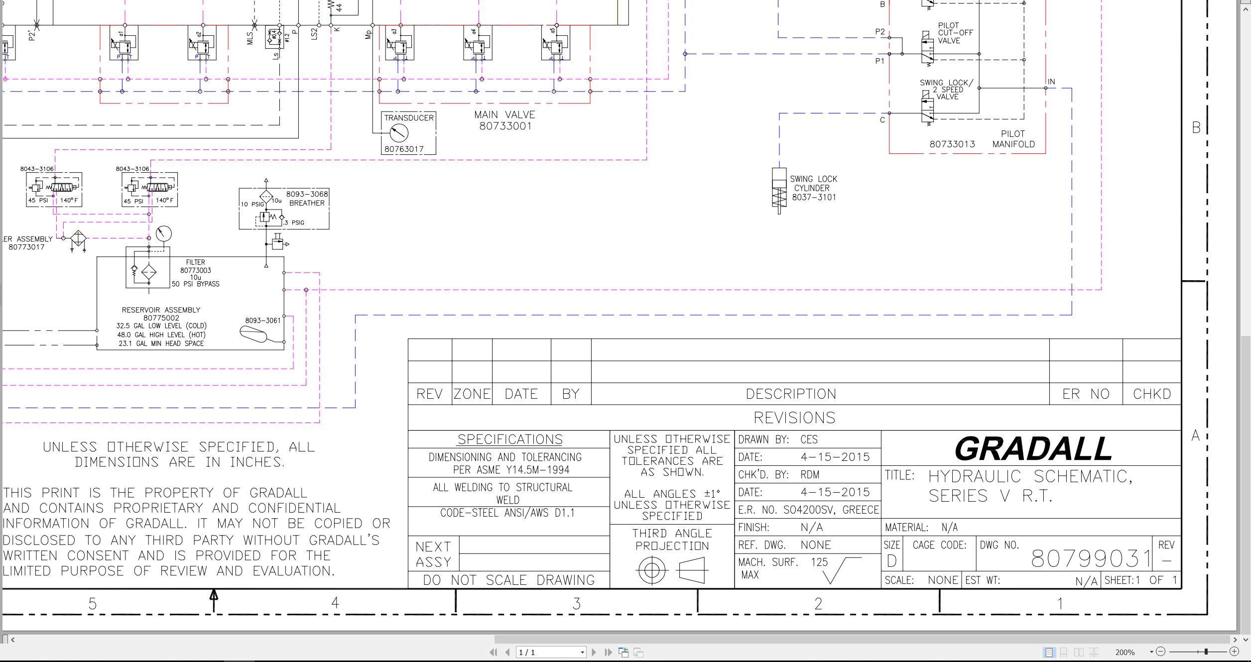
80799031 Hydraulic Schematic
WINCH
Winch Service Manual (S/N 4310000015)
Winch Service Manual (4340000101 & After)
DRIVE TRAIN
Front Axle Repair Manual
Front Axle Maintenance Instructions
Rear Axle Repair Manual
Rear Axle Maintenance Instructions
Transmission Repair Manual
Transmission Op & Maintenance
XL3300 to XL5330V Railgear Electrical Schematic 80799030.pdf (9 Pages)
XL3300V XL3300 ALTERRAIN XL3300V to XL3310 XL4310 INDUSTRIAL XL5330V Railgear Hydraulic Schematic 80799031.pdf (1 Pages)

REALEASE :
REALEASE :

REALEASE :
REALEASE :

REALEASE :
REALEASE :

REALEASE :
REALEASE :

REALEASE :
REALEASE :

REALEASE :
REALEASE :

REALEASE :
REALEASE :

REALEASE :
REALEASE :
 Automotive - Heavy Equipment - Truck & Bus - Forklift - Crane