
16 ITEMSVIEW CART


Total: 895.00
Expert Support
Full Speed
100% Working
30 USD
List of Files:
XL5100 XL5200 Operators Manual 2460-4068 .pdf (46 Pages)
Contents:
Introduction
General
Related Manuals & Decals
Operator Qualifications
Orientation
Pin Location
Safety Highlights
Decals Inside Cab
Decals Outside Cab
Operator’s Cab
Heater
Air Conditioner
Defrosting
Blower
Ventilation
Fire Extinguisher
Vdc Accessory Outlets
Control And Instrument Identification
Electronic Monitor
Checks And Services Before Starting Engine
Engine Operation
Starting Cummins Engine
Cold Weather Starting Aids
Normal Engine Operation
Stopping The Engine
Warm-Up & Operational Checks
Inside Front Cover
Attachment Installation
Remote Control
Preparing Carrier For Remote Control Operation
Preparing Upperstructure For Remote Control Operation
Precautions For Remote Control Operation
Driving Carrier From Upperstructure Cab
Preparing Upperstructure For Conventional Carrier Operation
Preparing Carrier For Conventional Operation
Crawler Mounted Units
Use Your Crawler Properly
Crawler Controls
How To Operate The Crawler
A Typical Gradall Digging Cycle
Lifting And Positioning A Load
Precautions
General
Positioning Machine For A Lift
Planning A Lift
Lubrication & Maintenance
Torque Chart
Recommended Lubricants & Capacities
Lubrication And Maintenance Diagram
Excavator Hand Signals
Securing Boom & Attachment For Travel
If You Get Stuck
XL5100 Chassis Operators Manual 2460-4069 2002.pdf (42 Pages)
Contents:
Important Safety Notice
Introduction
Safety Highlight
Instruments And Indicators
Controls
Checks And Services Before Starting Engine
Engine Operation
Checks After Starting Engine Checks before Driving
Plan Tour trip
brake System
Steering System
Power Train
Remote Control
Parking The Gradall
In Case of trouble
Lubrication
Checking Brake Adjustment
If You Get Stuck
XL5100 Parts Manual 2460-4070 2020.pdf (370 Pages)
Contents:
2460-4070 XL5100 PARTS MANUAL
UPPERSTRUCTURE
Section 1 Introduction
Section 2 Boom Assemblies
Section 3 Cab & Related Components
Section 4 Hydraulic System Components
Section 5 Main Hydraulic Systems
Section 6 Pilot Hydraulic Systems
Section 7 Attachments
UNDERCARRIAGE
Section 1 Introduction
Section 2 Undercarriage Assembly
Section 3 Drive Line Components
Section 4 Front Axle Assembly
Section 5 Rear Tandem Axle Assembly
Section 6 Air System
Section 7 Cab & Related Components
Section 8 Steering & Component Assemblies
OPTIONS
XL5100 Combined Service Manual 2460-4072 2002.pdf (1301 Pages)
Contents:
2460-4072 XL5100 COMBINED SERVICE MANUAL
OPERATOR INSTRUCTION
29114 Upperstructure Operation & Lube Manual
HYDRAULIC TESTING & ADJUSTMENT
RDE93010-02-R Rexroth Variable Displacement Pump Service Manual
RA64-774-S Rexroth Gear Pump Service Manual
RDE92002-30 Rexroth Swing Pump Service Manual
RDE 91001-01-R Rexroth Swing Motor/Remote Drive Motor Service Manual
RA64555 Rexroth Joystick
7-124 Char-Lynn Tilt Motor
MECHANICAL ADJUSTMENTS
29604 Upperstructure Mechanical Adjustments & Repair Manual
F36758 Ausco Swing Brake
S6A Fairfield Torque-Hub Service Manual
MISCELLANEOUS
29710 XL5000 Series Electrical Systems
8096-9001 Upper Wiring Diagram
F114004 Donaldson Cyclopac Service Procedure
OPERATOR INSTRUCTION
29115 XL5100 6X4 & 6X6 Operator & Lubrication Manual
STEERING
WA-TRW 1108 TRW Steering Gear Service Manual
I-3143-S Vickers Vane Pump Service Manual
CLUTCH
340186R Valeo Clutches Service Manual
MAIN TRANSMISSION
TRSM-0600RI Eaton/Fuller Driver Instructions
STEERING AXLE
MM#2 Rockwell Front Non-Drive Steering Axles
TP-97117 Rockwell Maintenance Manual Update
REAR TANDEM AXLE
TSA-2-113 Rockwell Axles w/Differential Lock Service Manual
MM#5L Rockwell Tandem Axle Forward Diff Carrier
FMM#5A Meritor Single Reduction Rear Differential Carriers
MM#1 Rockwell Lubrication Manual
TP-9303 Meritor Rockwell Advanced Lube Rear Drive Axles
TP-9238 Meritor Rockwell Driver-Controlled Diff Lock
DRIVE LINES
3264-2 Spicer U-Joints & Drive Shaft Service
TOL-006-95 Spicer U-Joints & Driveshafts Applications
BRAKE SYSTEM
8098-9002 Air Diagram
MM#4 Rockwell Cam-Master Cam Brakes
BW5057 Bendix Air Brake Handbook
SD-08-2403 Bendix AD-1 & AD-2 Air Dryers
WHEEL & RIM
0009 Rim & Wheel Safety Manual
1M-298 Webb Wheel Products
MISCELLANEOUS
F114005 Donaldson Air Cleaner Service
XL5100 Operator & Lubrication Manual 2460-4115 2004.pdf (42 Pages)
XL5100 Combined Service Manual 2460-4119 2006.pdf (1279 Pages)
Contents:
2460-4119 XL5100 COMBINED SERVICE MANUAL
OPERATOR INSTRUCTION
29114 Upperstructure Operation & Lube Manual
HYDRAULIC TESTING & ADJUSTMENT
RDE93010-02-R Rexroth Variable Displacement Pump Service Manual
RA64-774-S Rexroth Gear Pump Service Manual
RDE92002-30 Rexroth Swing Pump Service Manual
RDE 91001-01-R Rexroth Swing Motor/Remote Drive Motor Service Manual
RA64555 Rexroth Joystick
7-124 Char-Lynn Tilt Motor Service Manual
MECHANICAL ADJUSTMENTS
29604 Upperstructure Mechanical Adjustments & Repair Manual
F36758 Ausco Brake Technical Page
S6A Fairfield Torque-Hub Service Manual
MISCELLANEOUS
29710 XL4000/XL5000 Upperstructure Electrical System Manual
8096-9001 Upper Wiring Diagram
F114004 Donaldson Cyclopac Service Procedures
OPERATORS INSTRUCTION
29409 XL5000 6X4 & 6X6 Operator & Lubrication Manual
STEERING
WA-TRW 1108.pdf
I-3143-S Vickers Vane Pump Overhaul
CLUTCH
P.N. 340186R Valeo Clutch Installation
MAIN TRANSMISSION
TRSM-0600RI Eaton/Fuller DRRT-6613 Series Service Manual
FRONT AXLE
AXSM-0037 Eaton Steering Axle Service Manual
REAR TANDEM AXLE
TSA-2-113.pdf
MM#5L Rockwell Tandem Axle Differential Carriers Manual
FMM#5A Meritor Single Reduction Rear Differential Carriers
MM#1 Rockwell Lubrication
TP-9303 Meritor Advanced Lube Rear Drive Axles Pages
TP-9238 Meritor Driver-Controlled Diff Lock Pages
DRIVE LINES
3264-2 Spicer U-Joints & Driveshafts Service Manual
TOL-006-95 Spicer U-Joints & Driveshaft Service Manual
BRAKE SYSTEMS
8098-9002 Air Diagram
MM#4 Rockwell Cam-Master Brakes Manual
BW5057 Bendix Air Brake Handbook
SD-08-2403 Bendix Air Dryers Service Manual
MM#4B Rockwell Auto Slack Adjuster Manual
ABA-10003 Haldex Auto Brake Adjusters
4071 MGM Brakes
BRSM-0033 Eaton Automatic Slack Adjuster
WHEEL & RIM
0009 Rim & Wheel Safety Manual
1M-298 Webb Wheel Products
MISCELLANEOUS
F114005 Donaldson Air Cleaner Service
XL5100 CARRIER Chassis Operators Manual 2460-4132 2002.pdf (42 Pages)
Contents:
IMPORTANT SAFETY NOTICE
INTRODUCTION
General
Related Manuals
Operator Qualifications
Orientation
Serial Number Location
SAFETY HIGHLIGHTS
INSTRUMENTS AND INDICATORS
CONTROLS
CHECKS AND SERVICES BEFORE STARTING ENGINE
ENGINE OPERATION
Starting Diesel Engine
Cold Weather Starting Aids
Normal Engine Operation
Stopping the Engine
CHECKS AFTER STARTING THE ENGINE
CHECKS BEFORE DRIVING
PLAN YOUR TRIP
BRAKE SYSTEM
Service Brake
Emergency Brake
Parking Brake
Digging Brake
Remote Control Braking
STEERING SYSTEM
Conventional Steering
Remote Control Steering
POWER TRAIN
Shifting Gears
Inter-Axle Differential
REMOTE CONTROL
Preparing Carrier for Remote Control Operations
Preparing Upperstructure for Remote Control Operation
Precautions for Remote Control Operation
Driving Carrier from Upperstructure Cab
Preparing Upperstructure for Conventional Carrier Operation
Preparing Carrier for Conventional Operation
PARKING THE GRADALL
Precautions
IN CASE OF TROUBLE
Towing
IF YOU GET STUCK
LUBRICATION
6×4 Carrier Lubrication and Maintenance Diagram
6×6 Carrier Lubrication and Maintenance Diagram
Recommended Lubricants & Capacities
Torque Chart
CHECKING AUTOMATIC SLACK ADJUSTERS inside back cover
XL5100 Combined Service Manual 2460-4137 2006.pdf (1237 Pages)
Contents:
2460-4137 XL5100 COMBINED SERVICE MANUAL
OPERATOR INSTRUCTION
29619 Upperstructure Operation & Lube Manual
HYDRAULIC TESTING & ADJUSTMENT
RDE93010-02-R Rexroth Variable Displacement Pump Service Manual
RA64-774-S Rexroth Gear Pump Service Manual
RDE92002-30 Rexroth Swing Pump Service Manual
RDE 91001-01-R Rexroth Swing Motor/Remote Drive Motor Service Manual
RA64555 Rexroth Joystick
7-124 Char-Lynn Tilt Motor Service Manual
MECHANICAL ADJUSTMENTS
29604 Upperstructure Mechanical Adjustments & Repair Manual
F36758 Ausco Brake Technical Page
S6A Fairfield Torque-Hub Service Manual
MISCELLANEOUS
29710 XL5000 Series Electrical Systems
8096-9001 Upper Wiring Diagram
F114004 Donaldson Cyclopac Service Procedures
OPERATORS INSTRUCTION
29613 XL5000 6X4 & 6X6 Operators & Lubrication Manual
STEERING
WA-TRW 1108.pdf
I-3143-S Vickers Vane Pump Overhaul
CLUTCH
P.N. 340186R Valeo Clutch Installation
MAIN TRANSMISSION
TRDR0500 Eaton/Fuller Driver Instructions
RTO1190811 Eaton/Fuller Lubrication Sheet
FRONT AXLE
AXSM-0037 Eaton Steering Axle Service Manual
REAR TANDEM AXLE
TSA-2-113.pdf
MM#5L Rockwell Tandem Axle Differential Carriers Manual
FMM#5A Meritor Single Reduction Rear Differential Carriers
MM#1 Rockwell Lubrication
TP-9303 Meritor Advanced Lube Rear Drive Axles Pages
TP-9238 Meritor Driver-Controlled Diff Lock Pages
DRIVE LINES
3264-2 Spicer U-Joints & Driveshafts Service Manual
TOL-006-95 Spicer U-Joints & Driveshaft Service Manual
BRAKE SYSTEMS
8098-9002 Air Diagram
MM#4 Rockwell Cam-Master Brakes Manual
BW5057 Bendix Air Brake Handbook
SD-08-2403 Bendix Air Dryers Service Manual
MM#4B Rockwell Auto Slack Adjuster Manual
ABA-10003 Haldex Auto Brake Adjusters
4071 MGM Brakes
BRSM-0022 Dana Automatic Slack Adjuster
WHEEL & RIM
0009 Rim & Wheel Safety Manual
1M-298 Webb Wheel Products
MISCELLANEOUS
8098-9003 Chassis Wiring Diagram
F114005 Donaldson Air Cleaner Service
HE92-2 EMI Safety Manual
20013 Gradall Safety Manual
XL5100 Upper XL5200 Operators Manual 2460-4140 2002.pdf (45 Pages)
Contents:
IMPORTANT SAFETY NOTICE
INTRODUCTION
General
Related Manuals & Decals
Operator Qualifications
Orientation
PIN Location
SAFETY HIGHLIGHTS
DECALS INSIDE CAB
DECALS OUTSIDE CAB
OPERATOR’S CAB
Heater
Air Conditioner
Defrosting
Blower
Ventilation
Fire Extinguisher
12 VDC Accessory Outlets
CONTROL AND INSTRUMENT IDENTIFICATION
Electronic Monitor
CHECKS AND SERVICES BEFORE STARTING ENGINE
ENGINE OPERATION
Starting Cummins Engine
Cold Weather Starting Aids
Normal Engine Operation
Stopping the Engine
WARM-UP & OPTIONAL CHECKS
ATTACHMENTS INSTALLATION
REMOTE CONTROL
Preparing Carrier for Remote Control Operation
Preparing Upperstructure for Remote Control Operation
Precautions for Remote Control Operation
Driving Carrier From Upperstructure Cab
Preparing Upperstructure for Conventional Carrier Operation
Preparing Carrier for Conventional Operation
CRAWLER MOUNTED UNITS
Use Your Crawler Properly
Crawler Controls
How To Operate the Crawler
A TYPICAL GRADALL DIGGING CYCLE
LIFTING AND POSITIONING A LOAD
Precautions
General
Positioning Machine For A Lift
Planning A Lift
SECURING BOOM & ATTACHMENT FOR TRAVEL
IF YOU GET STUCK
EXCAVATOR HAND SIGNALS
LUBRICATION & MAINTENANCE
Torque Chart
Recommended Lubricants & Capacities
XL5100 Combined Service Manual 2460-4159 2006.pdf (1252 Pages)
Contents:
2460-4159 XL5100 COMBINED SERVICE MANUAL
OPERATOR INSTRUCTION
29619 Upperstructure Operation & Lube Manual
HYDRAULIC TESTING & ADJUSTMENT
8090-9022 Hydraulic Schematic
RDE93010-02-R Rexroth Variable Displacement Pump Service Manual
RA64-774-S Rexroth Gear Pump Service Manual
RDE92002-30 Rexroth Swing Pump Service Manual
RDE 91001-01-R Rexroth Swing Motor/Remote Drive Motor Service Manual
RA64555 Rexroth Joystick
7-124 Char-Lynn Tilt Motor Service Manual
MECHANICAL ADJUSTMENTS
29604 Upperstructure Mechanical Adjustments & Repair Manual
F36758 Ausco Brake Technical Page
S6A Fairfield Torque-Hub Service Manual
MISCELLANEOUS
29710 XL5000 Series Electrical Systems
8096-9001 Upper Wiring Diagram
F114004 Donaldson Cyclopac Service Procedures
OPERATORS INSTRUCTION
29613 XL5000 6X4 & 6X6 Operators & Lubrication Manual
STEERING
WA-TRW 1108.pdf
I-3143-S Vickers Vane Pump Overhaul
CLUTCH
P.N. 340186R Valeo Clutch Installation
CLWP-1707-4.pdf
MAIN TRANSMISSION
TRDR0500 Eaton/Fuller Driver Instructions
RTO1190811 Eaton/Fuller Lubrication Sheet
FRONT AXLE
AXSM-0037 Eaton Steering Axle Service Manual
REAR TANDEM AXLE
TSA-2-113.pdf
MM#5L Rockwell Tandem Axle Differential Carriers Manual
FMM#5A Meritor Single Reduction Rear Differential Carriers
MM#1 Rockwell Lubrication
TP-9303 Meritor Advanced Lube Rear Drive Axles Pages
TP-9238 Meritor Driver-Controlled Diff Lock Pages
DRIVE LINES
3264-2 Spicer U-Joints & Driveshafts Service Manual
TOL-006-95 Spicer U-Joints & Driveshaft Service Manual
BRAKE SYSTEMS
8098-9002 Air Diagram
MM#4 Rockwell Cam-Master Brakes Manual
BW5057 Bendix Air Brake Handbook
SD-08-2403 Bendix Air Dryers Service Manual
MM#4B Rockwell Auto Slack Adjuster Manual
ABA-10003 Haldex Auto Brake Adjusters
4071 MGM Brakes
BRSM-0022 Dana Automatic Slack Adjuster
WHEEL & RIM
0009 Rim & Wheel Safety Manual
1M-298 Webb Wheel Products
MISCELLANEOUS
8098-9003 Wiring Diagram
F114005 Donaldson Air Cleaner Service
HE92-2 EMI Safety Manual
20013 Gradall Safety Manual
XL5100 EPA Parts Manual 31200009 2004.pdf (293 Pages)
Contents:
31200009 XL5100 PARTS MANUAL
UPPERSTRUCTURE
Section 1 Introduction
Section 2 Boom Assemblies
Section 3 Cab & Related Components
Section 4 Hydraulic System Components
Section 5 Main Hydraulic Systems
Section 6 Pilot Hydraulic Systems
Section 7 Attachments
UNDERCARRIAGE
Section 1 Introduction
Section 2 Undercarriage Assembly
Section 3 Drive Line Components
Section 4 Front Axle Assembly
Section 5 Rear Tandem Axle Assembly
Section 6 Air System
Section 7 Cab & Related Components
Section 8 Steering & Component Assemblies
OPTIONS
XL5100 Illustrated Parts Manual 31200038 2005.pdf (516 Pages)
XL5100 Illustrated Parts Manual 31200052 2004.pdf (612 Pages)
XL5100 Illustrated Parts Manual 31200179 2005.pdf (516 Pages)
Contents:
31200179_XL5100_999268
Effectivity Page
Table of Contents
Section 1 Frame and Attaching Parts
Section 2 Boom
Section 3 Attachments
Section 4 Engine & Attaching Parts
Section 5 Drive Train
Section 6 Cab
Section 7 Controls
Section 8 Hydraulic Circuits
Section 9 Hydraulic Components
Section 10 Electrical
Section 11 Decals
Section 12 Options
Recommended Spare Parts
Part Number Index
XL5100 Illustrated Parts Manual 31200246 2006.pdf (524 Pages)
Contents:
XL5100 Parts Manual T#239726
Effectivity Page
Table of Contents
Service Kits
Section 1 Frame & Attaching Parts
Figure 1-1 Frame Assembly
Figure 1-2 Mirrors & Grab Rails
Figure 1-3 Engine Side Panels
Figure 1-4 R.H. Fender & Mirrors
Figure 1-5 L.H. Fender
Figure 1-6 Rear Fender Assembly
Figure 1-7 Deck & Cover
Figure 1-8 Steering Drag Link Assembly
Figure 1-9 Engine Sound Proofing Panels
Figure 1-10 Rotating Platform, L.H. View
Figure 1-11 Rotating Platform, R.H. View
Figure 1-12 Swing Bearing, Cradle & Hoist Cylinder Mounting & Lube System
Section 2 Boom
Figure 2-1 Boom Cradle
Figure 2-2 Main Boom Assembly
Figure 2-3 Telescope Boom Assembly
Figure 2-4 Inside Hose Trough
Figure 2-5 Roller Bracket Assembly
Figure 2-6 Bucket Linkage
Section 3 Attachments
Figure 3-1 28” Excavating Bucket
Figure 3-2 72” Ditching Bucket
Section 4 Engine & Attaching Parts
Figure 4-1 Engine Assembly, L.H. View, Upperstructure
Figure 4-2 Engine Assembly, R.H. View, Upperstructure
Figure 4-3 Engine Assembly, L.H. View, Undercarriage
Figure 4-4 Engine Assembly, R.H. View, Undercarriage
Figure 4-5 Air Cleaner Installation, Upperstructure
Figure 4-6 Air Cleaner Assembly, Upperstructure
Figure 4-7 Air Cleaner Assembly, Undercarriage
Figure 4-8 Power Steering Pump Reservoir
Figure 4-9 Exhaust System, Upperstructure
Figure 4-10 Exhaust System, Undercarriage
Figure 4-11 Fuel Tank Assembly, Upperstructure
Figure 4-12 Fuel Tank & Lines, Undercarriage
Figure 4-13 Oil Cooler, Radiator & Hoses, Upperstructure
Figure 4-14 Oil Filter Assembly
Figure 4-15 Oil Filter Assemblies
Figure 4-16 Radiator & Hoses, Undercarriage
Figure 4-17 Air Brake System
Figure 4-18 Upper Air System
Figure 4-19 Air System Component
Figure 4-20 Air System Components
Figure 4-21 Air System Components
Figure 4-22 Air System Components
Figure 4-23 Air System Components
Figure 4-24 Air System Components
Figure 4-25 Air System Components
Figure 4-26 Air Valve Assembly
Section 5 Drive Train
Figure 5-1 Clutch Assembly
Figure 5-2 Clutch Release Mechanism
Figure 5-3 Clutch Release Bearing
Figure 5-4 Transmission – Slave Control Assembly
Figure 5-5 Transmission – Slave Valve Assembly
Figure 5-6 Transmission – Shift Control Assembly
Figure 5-7 Transmission – Clutch Housing
Figure 5-8 Transmission – Shift Bar Housing
Figure 5-9 Transmission – Reverse Idle, Input Shaft & Drive Gear
Figure 5-10 Transmission – Mainshaft & Countershaft Gears
Figure 5-11 Transmission – Auxiliary Mainshaft
Figure 5-12 Transmission – Auxiliary Case Assembly
Figure 5-13 Transmission – Range Cylinder
Figure 5-14 Transmission – Auxiliary Countershaft & Auxiliary Drive Gear
Figure 5-15 Transmission – Master Shift Valve Assembly
Figure 5-16 Propeller Shaft
Figure 5-17 Transfer Case Assembly
Figure 5-18 Transfer Case – Input Shaft & Gear
Figure 5-19 Transfer Case – Intermediate Shaft & Gear Assembly
Figure 5-20 Transfer Case – Front Output Shaft Assembly
Figure 5-21 Transfer Case – Rear Output Shaft & Gear Assembly
Figure 5-22 Transfer Case – Front Declutch Shift Mechanism
Figure 5-23 Front Axle – Axle Assembly, 6×4
Figure 5-24 Front Axle – Steering Components, 6×4
Figure 5-25 Front Axle – Service Brakes, 6×4
Figure 5-26 Front Axle – Disc Wheels & Rims, 6×4
Figure 5-27 Front Axle – Axle Assembly, 6×6
Figure 5-28 Front Axle – Housing Assembly, 6×6
Figure 5-29 Front Axle – Differential Assembly, 6×6
Figure 5-30 Front Axle – Steering Components, 6×6
Figure 5-31 Front Axle – Service Brake, 6X6
Figure 5-32 Front Axle – Disc Wheel & Rims, 6×6
Figure 5-33 Front Axle – Spring Assembly
Figure 5-34 Rear Axle – Axle Assembly
Figure 5-35 Rear Axle – Axle Housing Assembly
Figure 5-36 Rear Axle – Forward Differential Assembly
Figure 5-37 Rear Axle – Rear Differential Assembly
Figure 5-38 Rear Axle – Service Brakes
Figure 5-39 Rear Axle – Disc Wheels & Rims
Figure 5-40 Equalizer Beam
Section 6 Cab
Figure 6-1 Operators Cab, Upperstructure
Figure 6-2 Cab Door, Upperstructure
Figure 6-3 Cab Accoustical Liners, Upperstructure
Figure 6-4 Cab Console
Figure 6-5 Cab Seat, Upperstructure
Figure 6-6 Cab Heater & Installation, Upperstructure
Figure 6-7 Operators Cab, Undercarriage
Figure 6-8 Cab Door, Undercarriage
Figure 6-9 Cab Accoustical Liners, Undercarriage
Figure 6-10 Cab Seat, Undercarriage
Figure 6-11 Windshield Wiper & Washer
Figure 6-12 Cab Heater & Defroster, Undercarriage
Section 7 Controls
Figure 7-1 Joystick Assembly
Figure 7-2 Steering Column Assembly
Figure 7-3 Steering Drive Shaft
Figure 7-4 Foot Pedals & Installation
Figure 7-5 Foot Operated Pedal Valve Assembly
Figure 7-6 Accelerator Pedal & Linkage
Section 8 Hydraulic Circuits
Figure 8-1 Oil Supply to Pumps
Figure 8-2 Hydraulic Pressure to Control Valves
Figure 8-3 Hydraulic Hosing To Joystick & Foot Operated Valves
Figure 8-4 Dump Circuit
Figure 8-5 Hoist Pilot
Figure 8-6 Boom Pilot
Figure 8-7 Tool Pilot
Figure 8-8 Propel Pilot
Figure 8-9 Hoist Cylinder
Figure 8-10 Boom Cylinder
Figure 8-11 Tool Cylinder
Figure 8-12 Swing & Swing Brake
Figure 8-13 Upper Propelling
Figure 8-14 Upper Steering
Figure 8-15 Swing Motor
Figure 8-16 Tilt Motor
Figure 8-17 Steering Gear
Figure 8-18 Remote Control Travel
Figure 8-19 Remote Steering
Figure 8-20 Stabilizer Cylinder
Figure 8-21 Oil Filter & Hosing
Section 9 Hydraulic Components
Figure 9-1 Hoist Cylinder Assembly
Figure 9-2 Boom Cylinder Assembly
Figure 9-3 Tool Cylinder Assembly
Figure 9-4 Stabilizer Cylinder Assembly
Figure 9-5 Stabilizer Valve Assembly
Figure 9-6 Remote Steering Hydraulic Cylinder Assembly
Figure 9-7 Main Pump – Front
Figure 9-8 Main Pump – Rear
Figure 9-9 Directional Control Valve Assembly
Figure 9-10 Boom & Propel Control Valve Assembly
Figure 9-11 Boom Valve Section Assembly
Figure 9-12 Propel Valve Section Assembly
Figure 9-13 Hoist, Tilt, Tool Control Valve Assembly
Figure 9-14 Hoist Valve Section Assembly
Figure 9-15 Tilt Valve Section Assembly
Figure 9-16 Tool Valve Section Assembly
Figure 9-17 Auxiliary Valve Section Assembly
Figure 9-18 Gear Pump Assembly
Figure 9-19 Reservoir Assembly
Figure 9-20 Swing Pump
Figure 9-21 Swing Pump
Figure 9-22 Swing Pump
Figure 9-23 Swing Pump
Figure 9-24 Swing Transmission Installation
Figure 9-25 Swing Transmission
Figure 9-26 Swing Motor
Figure 9-27 Swing Brake
Figure 9-28 Swing Brake Release Valve
Figure 9-29 Tilt Transmission Assembly
Figure 9-30 Tilt Motor
Figure 9-31 Center Pin Assembly
Figure 9-32 Power Take-Off
Figure 9-33 Power Take-Off Housing
Figure 9-34 Power Take-Off Output Shaft & Bearing Cap
Figure 9-35 Power Take-Off Air Shift
Figure 9-36 Power Take-Off Drive Motor
Figure 9-37 Steering Valve Assembly
Figure 9-38 Power Steering Pump
Figure 9-39 Valve Assembly
Figure 9-40 Pilot/Steer Valve
Figure 9-41 Thermal By-Pass Valve
Figure 9-42 Pressure Reducing Valve Assembly
Figure 9-43 Pressure Reducing Valve
Figure 9-44 Solenoid Valve Assembly
Figure 9-45 Clamp Sets & Miscellaneous Hydraulic Components
Figure 9-46 Steering Gear
Section 10 Electrical
Figure 10-1 Batteries & Miscellaneous Electrical Components
Figure 10-2 Distribution Box
Figure 10-3 Battery Box, Batteries & Cables
Figure 10-4 Tail & Marker Lights
Figure 10-5 Head & Marker Lights
Figure 10-6 Horn & Miscelleous
Figure 10-7 Instrument Panel Assembly
Figure 10-8 Accessory Panel Assembly
Section 11 Decals
Figure 11-1 Decals, Upperstructure
Figure 11-2 Decals, Undercarriage
Section 12 Options
Figure 12-1 Air Conditioner, Upperstructure
Figure 12-2 Air Seat Installation Components, Undercarriage
Figure 12-3 Auxiliary Fan Installation Components, Upperstructure
Figure 12-4 Auxiliary Oil Cooler Installation Components, Upperstructure
Figure 12-5 Battery Disconnect Switch Installation, Upperstructure
Figure 12-6 Engine Block Heater Installation Components, Upperstructure
Figure 12-7 Engine Block Heater Installation Components, Undercarriage
Figure 12-8 Engine Shutdown Installation Components, Upperstructure
Figure 12-9 Engine Shutdown Installation Components, Undercarriage
Figure 12-10 Floodlight Installation Components, Upperstructure
Figure 12-11 Four-Line Hose Trough Installation Components, Upperstructure
Figure 12-12 Rear Tow Hook Installation Components, Undercarriage
Figure 12-13 Seat Belt Installation Components, Upperstructure
Figure 12-14 Valve Module Auxiliary Hydraulics Installation Components, Upperstructure
Figure 12-15 Windows Cover Installation Components, Undercarriage
Figure 12-16 Wiper/Washer Installation Components, Upperstructure
Figure 12-17 Operating Decals
Figure 12-18 Vandal Cover Installation Components, Undercarriage
Figure 12-19 Strobe Light Installation
Figure 12-20 Battery Disconnect Switch
Figure 12-21 Air Conditioning, Undercarriage
Recommended Spare Parts
Part Number Index
XL5100 EPA Illustrated Parts Manual 51004001 2023.pdf (624 Pages)
Contents:
51004001_U_XL5100EPA_Gradall_Parts_10-2023
Effectivity Page
Table of Contents
Service Kits
Section 1 Frame & Attaching Parts
Figure 1-1 Frame Assembly
Figure 1-2 Mirrors & Grab Rails
Figure 1-3 Engine Side Panels
Figure 1-4 R.H. Fender & Mirrors
Figure 1-5 L.H. Fender
Figure 1-6 Rear Fender Assembly
Figure 1-7 Deck & Cover
Figure 1-8 Steering Drag Link Assembly
Figure 1-9 Engine Sound Proofing Panels
Figure 1-10 Rotating Platform, L.H. View
Figure 1-11 Rotating Platform, R.H. View
Figure 1-12 Swing Bearing, Cradle & Hoist Cylinder Mounting & Lube System
Section 2 Boom
Figure 2-1 Boom Cradle
Figure 2-2 Main Boom Assembly
Figure 2-3 Telescope Boom Assembly
Figure 2-4 Inside Hose Trough
Figure 2-5 Roller Bracket Assembly
Figure 2-6 Bucket Linkage
Section 3 Attachments
Figure 3-1 28” Excavating Bucket
Figure 3-2 36” Excavating Bucket
Figure 3-3 48” Excavating Bucket
Figure 3-4 24” Ditching Bucket & 8’ Grading Blade
Figure 3-5 48” Pavement Removal Bucket
Figure 3-6 66” Ditching Bucket
Figure 3-7 72” Ditching Bucket
Figure 3-8 108” Dredging Bucket
Figure 3-9 15” Trenching Bucket
Figure 3-10 Single Tooth Ripper
Figure 3-11 Rock Bucket Assembly
Figure 3-12 6’ Boom Extension
Figure 3-13 8’ Boom Extension Assembly
Figure 3-14 12’ Boom Extension Assembly
Figure 3-15 Telestick Assembly
Figure 3-16 Grapple Assembly
Figure 3-17 Attachment Adapter, Female
Section 4 Engine & Attaching Parts
Figure 4-1 Engine Assembly, L.H. View, Upperstructure
Figure 4-2 Engine Assembly, R.H. View, Upperstructure
Figure 4-3 Engine Assembly, L.H. View, Undercarriage
Figure 4-4 Engine Assembly, R.H. View, Undercarriage
Figure 4-5 Air Cleaner Installation, Upperstructure
Figure 4-6 Air Cleaner Assembly, Upperstructure
Figure 4-7 Air Cleaner Assembly, Undercarriage
Figure 4-8 Power Steering Pump Reservoir
Figure 4-9 Exhaust System, Upperstructure
Figure 4-10 Exhaust System, Undercarriage
Figure 4-11 Fuel Tank Assembly, Upperstructure
Figure 4-12 Fuel Tank & Lines, Undercarriage
Figure 4-13 Oil Cooler, Radiator & Hoses, Upperstructure
Figure 4-14 Oil Filter Assembly
Figure 4-15 Oil Filter Assemblies
Figure 4-16 Radiator & Hoses, Undercarriage
Figure 4-17 Air Brake System
Figure 4-18 Upper Air System
Figure 4-19 Air System Component
Figure 4-20 Air System Components
Figure 4-21 Air System Components
Figure 4-22 Air System Components
Figure 4-23 Air System Components
Figure 4-24 Air System Components
Figure 4-25 Air System Components
Figure 4-26 Air Valve Assembly
Section 5 Drive Train
Figure 5-1 Clutch Assembly
Figure 5-2 Clutch Release Mechanism
Figure 5-3 Clutch Release Bearing
Figure 5-4 Transmission – Slave Control Assembly
Figure 5-5 Transmission – Slave Valve Assembly
Figure 5-6 Transmission – Shift Control Assembly
Figure 5-7 Transmission – Clutch Housing
Figure 5-8 Transmission – Shift Bar Housing
Figure 5-9 Transmission – Reverse Idle, Input Shaft & Drive Gear
Figure 5-10 Transmission – Mainshaft & Countershaft Gears
Figure 5-11 Transmission – Auxiliary Mainshaft
Figure 5-12 Transmission – Auxiliary Case Assembly
Figure 5-13 Transmission – Range Cylinder
Figure 5-14 Transmission – Auxiliary Countershaft & Auxiliary Drive Gear
Figure 5-15 Transmission – Master Shift Valve Assembly
Figure 5-16 Propeller Shaft
Figure 5-17 Transfer Case Assembly
Figure 5-18 Transfer Case – Input Shaft & Gear
Figure 5-19 Transfer Case – Intermediate Shaft & Gear Assembly
Figure 5-20 Transfer Case – Front Output Shaft Assembly
Figure 5-21 Transfer Case – Rear Output Shaft & Gear Assembly
Figure 5-22 Transfer Case – Front Declutch Shift Mechanism
Figure 5-23 Front Axle – Axle Assembly, 6×4
Figure 5-24 Front Axle – Steering Components, 6×4
Figure 5-25 Front Axle – Service Brakes, 6×4
Figure 5-26 Front Axle – Disc Wheels & Rims, 6×4
Figure 5-27 Front Axle – Axle Assembly, 6×6
Figure 5-28 Front Axle – Housing Assembly, 6×6
Figure 5-29 Front Axle – Differential Assembly, 6×6
Figure 5-30 Front Axle – Steering Components, 6×6
Figure 5-31 Front Axle – Service Brake, 6X6
Figure 5-32 Front Axle – Disc Wheel & Rims, 6×6
Figure 5-33 Front Axle – Spring Assembly
Figure 5-34 Rear Axle – Axle Assembly
Figure 5-35 Rear Axle – Axle Housing Assembly
Figure 5-36 Rear Axle – Forward Differential Assembly
Figure 5-37 Rear Axle – Rear Differential Assembly
Figure 5-38 Rear Axle – Service Brakes
Figure 5-39 Rear Axle – Disc Wheels & Rims
Figure 5-40 Equalizer Beam
Section 6 Cab
Figure 6-1 Operators Cab, Upperstructure
Figure 6-2 Cab Door, Upperstructure
Figure 6-3 Cab Accoustical Liners, Upperstructure
Figure 6-4 Cab Console
Figure 6-5 Cab Seat, Upperstructure
Figure 6-6 Cab Heater & Installation, Upperstructure
Figure 6-7 Operators Cab, Undercarriage
Figure 6-8 Cab Door, Undercarriage
Figure 6-9 Cab Accoustical Liners, Undercarriage
Figure 6-10 Cab Seat, Undercarriage
Figure 6-11 Windshield Wiper & Washer
Figure 6-12 Cab Heater & Defroster, Undercarriage
Section 7 Control
Figure 7-1 Joystick Assembly
Figure 7-2 Steering Column Assembly
Figure 7-3 Steering Drive Shaft
Figure 7-4 Foot Pedals & Installation
Figure 7-5 Foot Operated Pedal Valve Assembly
Figure 7-6 Accelerator Pedal & Linkage
Section 8 Hydraulic Circuits
Figure 8-1 Oil Supply to Pumps
Figure 8-2 Hydraulic Pressure to Control Valves
Figure 8-3 Hydraulic Hosing To Joystick & Foot Operated Valves
Figure 8-4 Dump Circuit
Figure 8-5 Hoist Pilot
Figure 8-6 Boom Pilot
Figure 8-7 Tool Pilot
Figure 8-8 Propel Pilot
Figure 8-9 Hoist Cylinder
Figure 8-10 Boom Cylinder
Figure 8-11 Tool Cylinder
Figure 8-12 Swing & Swing Brake
Figure 8-13 Upper Propelling
Figure 8-14 Upper Steering
Figure 8-15 Swing Motor
Figure 8-16 Tilt Motor
Figure 8-17 Steering Gear
Figure 8-18 Remote Control Travel
Figure 8-19 Remote Steering
Figure 8-20 Stabilizer Cylinder
Figure 8-21 Oil Filter & Hosing
Section 9 Hydraulic Components
Figure 9-1 Hoist Cylinder Assembly
Figure 9-2 Boom Cylinder Assembly
Figure 9-3 Tool Cylinder Assembly
Figure 9-4 Stabilizer Cylinder Assembly
Figure 9-5 Stabilizer Valve Assembly
Figure 9-6 Remote Steering Hydraulic Cylinder Assembly
Figure 9-7 Main Pump – Front
Figure 9-8 Main Pump – Rear
Figure 9-9 Directional Control Valve Assembly
Figure 9-10 Boom & Propel Control Valve Assembly
Figure 9-11 Boom Valve Section Assembly
Figure 9-12 Propel Valve Section Assembly
Figure 9-13 Hoist, Tilt, Tool Control Valve Assembly
Figure 9-14 Hoist Valve Section Assembly
Figure 9-15 Tilt Valve Section Assembly
Figure 9-16 Tool Valve Section Assembly
Figure 9-17 Auxiliary Valve Section Assembly
Figure 9-18 Gear Pump Assembly
Figure 9-19 Reservoir Assembly
Figure 9-20 Swing Pump Assembly (80933003)
Figure 9-21 Swing Pump Assembly (80933317)
Figure 9-22 Swing Pump Assembly (80933070)
Figure 9-23 Swing Transmission Installation
Figure 9-24 Swing Transmission
Figure 9-25 Swing Motor
Figure 9-26 Swing Brake
Figure 9-27 Swing Brake Release Valve
Figure 9-28 Tilt Transmission Assembly
Figure 9-29 Tilt Motor
Figure 9-30 Center Pin Assembly
Figure 9-31 Power Take-Off
Figure 9-32 Power Take-Off Housing
Figure 9-33 Power Take-Off Output Shaft & Bearing Cap
Figure 9-34 Power Take-Off Air Shift
Figure 9-35 Power Take-Off Drive Motor
Figure 9-36 Steering Valve Assembly
Figure 9-37 Power Steering Pump
Figure 9-38 Valve Assembly
Figure 9-39 Pilot/Steer Valve
Figure 9-40 Thermal By-Pass Valve
Figure 9-41 Pressure Reducing Valve Assembly
Figure 9-42 Pressure Reducing Valve
Figure 9-43 Clamp Sets & Miscellaneous Hydraulic Components
Figure 9-44 Steering Gear
Section 10 Electrical
Figure 10-1 Batteries & Miscellaneous Electrical Components
Figure 10-2 Distribution Box
Figure 10-3 Battery Box, Batteries & Cables
Figure 10-4 Tail & Marker Lights
Figure 10-5 Head & Marker Lights
Figure 10-6 Horn & Miscellaneous
Figure 10-7 Instrument Panel Assembly
Figure 10-8 Accessory Panel Assembly
Section 11 Decals
Figure 11-1 Decals, Upperstructure
Figure 11-2 Decals, Undercarriage
Section 12 Options
Figure 12-1 Air Conditioner, Upperstructure
Figure 12-2 Air Conditioning Evaporator Kit
Figure 12-3 Air Filter Restriction Gauge, Undercarriage
Figure 12-4 Air Seat Installation Components, Undercarriage
Figure 12-5 Auxiliary Fan Installation Components, Upperstructure
Figure 12-6 Auxiliary Hydraulic Valve Field Installation Components, Upperstructure
Figure 12-7 Auxiliary Oil Cooler Installation Components, Upperstructure
Figure 12-8 Additional Battery Installation Components
Figure 12-9 Battery Disconnect Switch Installation, Upperstructure
Figure 12-10 Cold Start Installation Components, Upperstructure
Figure 12-11 Cold Start Installation Components, Undercarriage
Figure 12-12 Engine Alarm Installation Components, Undercarriage
Figure 12-13 Engine Block Heater Installation Components, Upperstructure
Figure 12-14 Engine Block Heater Installation Components, Undercarriage
Figure 12-15 Engine Shutdown Installation Components, Upperstructure
Figure 12-16 Engine Shutdown Installation Components, Undercarriage
Figure 12-17 Floodlight Installation Components, Upperstructure
Figure 12-18 Four-Line Hose Trough Installation Components, Upperstructure
Figure 12-19 Four-Line Hose Trough Installation Components, Upperstructure
Figure 12-20 Roof Hatch Installation Components, Upperstructure
Figure 12-21 Rear Tow Hook Installation Components, Undercarriage
Figure 12-22 Seat Belt Installation Components, Upperstructure
Figure 12-23 Spark Arrestor Installation Components, Undercarriage
Figure 12-24 Spark Arrestor Installation, Upperstructure
Figure 12-25 Strobe Light Installation, Undercarriage
Figure 12-26 Turbo ll Precleaner Installation Components, Undercarriage
Figure 12-27 Valve Module Auxiliary Hydraulics Installation Components, Upperstructure
Figure 12-28 Vandal Cover Installation, Upperstructure
Figure 12-29 Windows Cover Installation Components, Undercarriage
Figure 12-30 Vandal Cover Installation Components, Undercarriage
Figure 12-31 Reservoir Vandal Cover Installation, Upperstructure
Figure 12-32 Wiper/Washer Installation Components, Upperstructure
Figure 12-33 Operating Decals
Recommended Spare Parts
Part Number Index
XL3100 XL3100IV XL4100 XL4100IV XL5100IV to XL5130V Railgear Hydraulic Schematic 80709006.pdf (2 Pages)
XL4100V XL3100V XL4100V XL3100V to XL3100V XL3100 XL4100V Electrical Schematic 80709015.pdf (12 Pages)
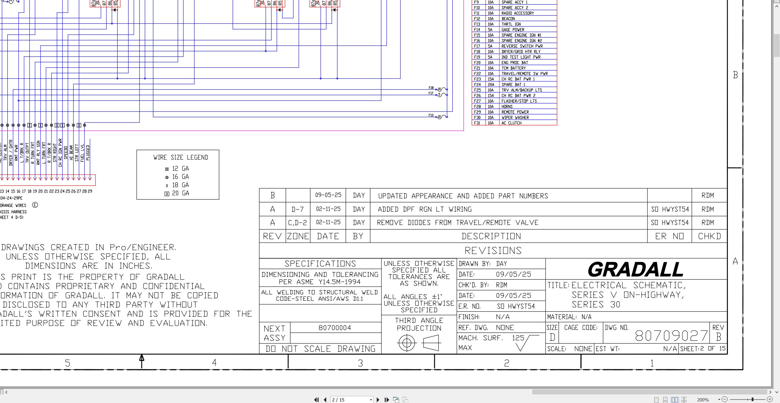
XL4100V XL4100 XL4100V to XL3100V XL3100 XL3100V XL3100 XL3100V Electrical Schematic 80709027.pdf (15 Pages)
XL4100V XL4100 XL4100V to XL3100V XL3100 XL3100V XL3100 XL3100V Electrical Schematic 80709027.pdf (15 Pages)
XL4100 XL4100V XL5100 XL5100V Air Schematic 80789164.pdf (1 Pages)
XL4100 XL4100V XL5100 XL5100V Air Schematic 80789259.pdf (1 Pages)
Series V XL3100V XL4100V XL5100V XL3100 XL4100 XL5100 Illustrated Parts Manual 80884032 2026.pdf (778 Pages)
Contents:
Section 1 – Frame & Attaching Parts
Section 2 – Boom
Section 3 – Attachments
Section 4 – Engine & Attaching Parts
Section 5 – Drive Train
Section 6 – Cab
Section 7 – Controls
Section 8 – Hydraulic Circuits
Section 9 – Hydraulic Components
Section 10 – Electrical
Section 11 – Decals
Recommended Spare Parts
Part Number Index
Series V XL3100V XL4100V XL5100V XL3100 XL4100 XL5100 Operator Safety Manual 80884033 2026.pdf (172 Pages)
Contents:
Section 1 – General Safety Practices
1.1 Hazard Classification System
1.2 General Precautions
1.3 Operation Safety
1.4 Personal Protection Equipment
Section 2 – Pre-Operation and Controls
2.1 Pre-Operation Checks & Inspection
2.2 Walk-Around Inspection
2.3 Safety Decals
2.4 Undercarriage Cab Components
2.5 Transmission Shift Selector
2.6 Undercarriage Cab Controls & Indicators
2.7 Upperstructure Cab Components
2.8 Upperstructure Cab Controls & Indicators
Section 3 – Operation
3.1 Travel Mode Engine Operation
3.2 Checks Before Undercarriage Operation
3.3 Travel Mode Brake System
3.4 Travel Mode Power Train
3.5 Travel Mode Engine Shutdown
3.6 Remote Control Preparation
3.7 Checks Before Remote Control Operation
3.8 Remote Mode Brake System
3.9 Remote Mode Power Train
3.10 Steering System
3.11 Typical Dig Cycle
3.12 Lifting & Placing a Load
3.13 Lift Capacity
3.14 Remote Mode Engine Shutdown
3.15 Return to Travel Mode
3.16 Parking the Excavator
3.17 Preservation & Storage
3.18 Parked Regeneration (Stage V Engines)
Section 4 – Attachments
4.1 Approved Attachments
4.2 Unapproved Attachments
4.3 Attachment Operation
4.4 Adapter Attachment Installation
Section 5 – Lubrication & Maintenance
5.1 Introduction
5.2 General Maintenance Instructions
5.3 Service & Maintenance Schedules
5.4 Undercarriage Lubrication Schedules
5.5 Upperstructure Lubrication Schedules
5.6 Operator Maintenance Instructions
Section 6 – Emergency Procedures
6.1 Loss Of Power
Section 7 – Specifications
7.1 Product Specifications
7.2 Torque Chart
7.3 Fuses
Index
Series V XL3100V XL4100V XL5100V XL3100 XL4100 XL5100 Service Manual 80884034 2026.pdf (1189 Pages)
Contents:
80884034_C_Series V Highway Speed Combined Service Manual_3-2026
VOLUME I
80884033_C_Series V Highway Speed Op & Safety Manual_3-2026
HYDRAULIC TEST & ADJUSTMENT
MECHANICAL ADJUSTMENT
ELECTRICAL
STEERING
MAIN TRANSMISSION
VOLUME II
FRONT AXLE
REAR AXLE
DRIVE LINES
BRAKE SYSTEMS
MISCELLANEOUS
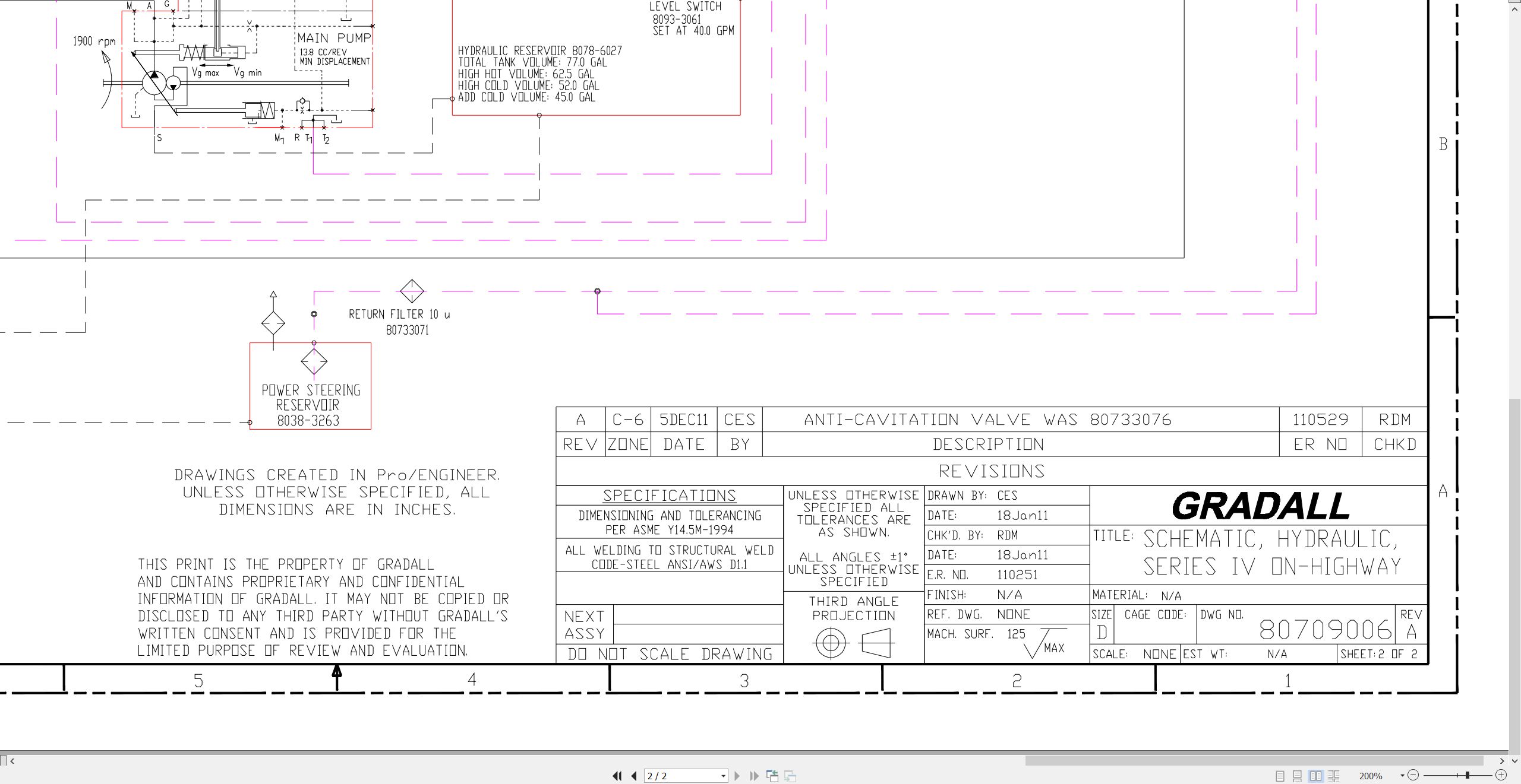
XL5100 Hydraulic Schematic 80909022 2000.pdf (1 Pages)
XL4100 XL5100 Air Diagram 80989002 2001.pdf (1 Pages)
XL4100 XL5100 Chassis Electric Schematic 80989003 2001.pdf (1 Pages)

REALEASE :
REALEASE :

REALEASE :
REALEASE :

REALEASE :
REALEASE :

REALEASE :
REALEASE :

REALEASE :
REALEASE :

REALEASE :
REALEASE :

REALEASE :
REALEASE :

REALEASE :
REALEASE :
 Automotive - Heavy Equipment - Truck & Bus - Forklift - Crane