
0 ITEMSVIEW CART

✓
Expert Support
✓
Full Speed
✓
100% Working
Gradall Excavator XL5100III Operators Parts Service Manual
Size: 165.90 MB
Format: PDF
Language: English
Brand: Gradall
Type of Machine: Highway-speed Wheeled Hydraulic Excavator
Type of Manual: Air Diagram, Air Schematic, Electrical Schematic, Hydraulic Schematic, Illustrated Parts Manual, Operator Safety Manual, Parts Manual, Service Manual
Model: Gradall XL5100III Highway-speed Wheeled Hydraulic Excavator
30 USD
- Description
Description
List of Files:
XL4100III XL5100III Air Diagram 3540008.pdf (1 Pages)
XL4100III XL5100III Air Schematic 3540009.pdf (1 Pages)
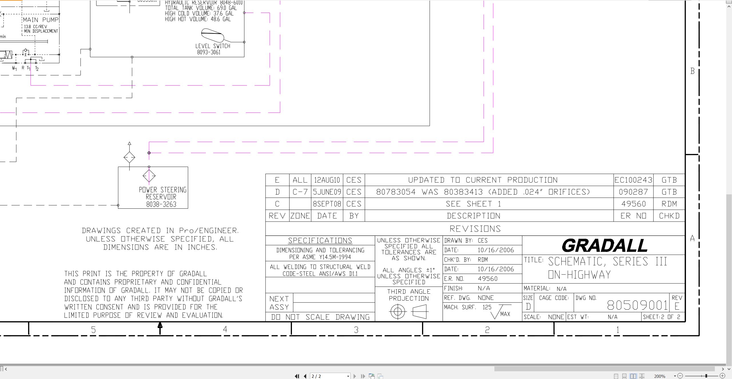
XL3100III XL3100 XL4100III XL5100III Hydraulic Schematic 80509001.pdf (2 Pages)
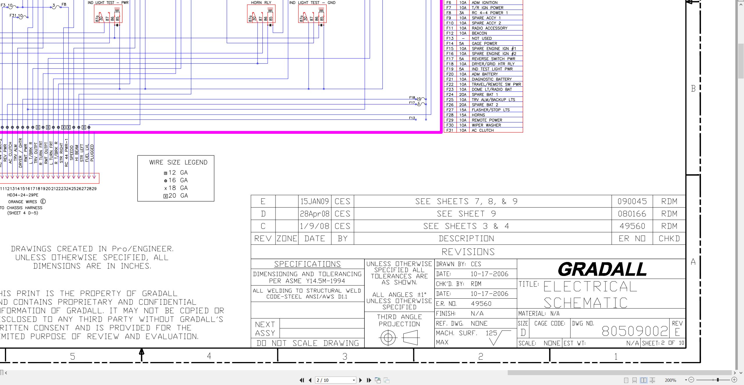
XL3100III XL3100 XL4100III XL5100III Electrical Schematic 80509002.pdf (10 Pages)
Series III XL3100III XL4100III XL5100III Illustrated Parts Manual 80854001 2026.pdf (864 Pages)
Contents:
80854001_AC_Series III Highway Speed Excavators_Parts Manual_3-2026
Understanding Your Manual
Section 1 – Frame & Attaching Parts
Section 2 – Boom
Section 3 – Attachments
Section 4 – Engine & Attaching Parts
Section 5 – Drive Train
Section 6 – Cab
Section 7 – Controls
Section 8 – Hydraulic Circuits
Section 9 – Hydraulic Components
Section 10 – Electrical
Section 11 – Decals
Section 12 – Options
Recommended Spare Parts
Part Number Index
Series III XL3100III XL4100III XL5100III Operator Safety Manual 80854002 2024.pdf (166 Pages)
Contents:
Section 1 – General Safety Practices
1.1 Hazard Classification System
1.2 General Precautions
1.3 Operation Safety
1.4 Personal Protection Equipment
Section 2 – Pre-Operation and Controls
2.1 Pre-Operation Checks & Inspection
2.2 Walk-Around Inspection
2.3 Safety Decals
2.4 Undercarriage Cab Components
2.5 Undercarriage Cab Controls & Indicators
2.6 Upperstructure Cab Components
2.7 Upperstructure Cab Controls & Indicators
Section 3 – Operation
3.1 Travel Mode Engine Operation
3.2 Checks Before Undercarriage Operation
3.3 Travel Mode Brake System
3.4 Travel Mode Power Train
3.5 Travel Mode Engine Shutdown
3.6 Remote Control Preparation
3.7 Checks Before Remote Control Operation
3.8 Remote Mode Brake System
3.9 Remote Mode Power Train
3.10 Steering System
3.11 Typical Dig Cycle
3.12 Lifting & Placing a Load
3.13 Lift Capacity
3.14 Remote Mode Engine Shutdown
3.15 Return to Travel Mode
3.16 Parking the Excavator
3.17 Preservation & Storage
Section 4 – Attachments
4.1 Approved Attachments
4.2 Unapproved Attachments
4.3 Attachment Operation
4.4 Adapter Attachment Installation
Section 5 – Lubrication & Maintenance
5.1 Introduction
5.2 General Maintenance Instructions
5.3 Service & Maintenance Schedules
5.4 Undercarriage Lubrication Schedules
5.5 Upperstructure Lubrication Schedules
5.6 Operator Maintenance Instructions
Section 6 – Emergency Procedures
6.1 Loss Of Power
Section 7 – Specifications
7.1 Product Specifications
7.2 Torque Chart
7.3 Fuses
Pre-Operation Inspection Checklist
Index
Series III XL3100III XL4100III XL5100III Service Manual 80854003 2024.pdf (504 Pages)
Contents:
Alphabetical Index
Operators Manual
80854002 F Series III Highway Speed Operation & Safety Manual 1-2024
Hydraulic Section
Hydraulic System Operation Manual
Hydraulic Pressure Adjustment Manual
Final Test Report
Shipping Inspection Checklist
Electrical Section
Gradall Bodas-Service Installation & Operation
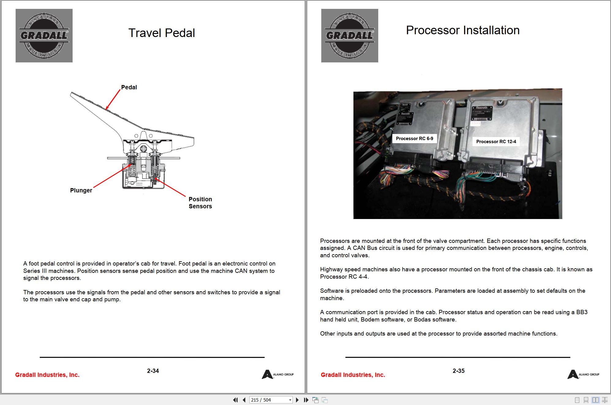
On-Highway Electrical Switch Locations
Highway Speed Processor Operation
Mechanical Section
Tool Kit
Emergency Procedures
Pressure Test Kits
Recommended Lubricants & Capacities
Torque Chart
Boom Assembly Identification
Boom Cylinder Slide Pads
Boom Roller Adjustment
Boom Assembly Tool Eye & Adapter
Tool Cylinder & Auxiliary Circuit Hose Alignment
Transmission Oil Level
Axle Lubrication Information
Axle Oil Level
Transfer Case Lubrication
Air Dryer Maintenance
Clutch Adjustment Procedure
Transmission Shift Cable Adjustment
Brake Chambers
Mercedes Benz 900 Series Engine Oil Pan Drain Plugs
Fan Clutch Maintenance
Swing Transmission Lubricant Check & Refill Requirements
Swing Transmission Fill Illustration
Rear Axle Walking Beam Clearance
Remote Drive PTO Removal & Replacement
Torque Values & Tolerances for Lubricated English Bolts
Climate Control section
Gradall Highway Speed Climate Control System
System Safety
Hydraulic vs. Engine Drive
Typical A/C System Circuit
Compressor
Condenser
Receiver – Dryer
Expansion Valve
Evaporator
Thermostat
High Side/Low Side
Pressure Switch
Hydraulically Driven A/C Unit
Upper Climate Controls
AC/Heater Assembly – Cab Assembly
AC/Heater Valve Assembly – Highway Speed
Hydraulic Heater Unit – Highway Speed Excavator
Water Valve
Water Control Valve
Lower Climate Controls
AC System Receiver Dryers
AC System Receiver Dryers Directional Designation
R134a A/C Systems & Compressed Air
A/C System Moisture Contamination
4923354 (B) Chassis Cab Harness
4923322 (G) Chassis Harness
4923453 (C) Dash Harness
4923323 (C) Engine Harness
80509001 (E) Hydraulic Schematic
80509002 (E) Electrical Schematic
4923454 (A) Switch Panel Harness
80609016 (B) Hydraulic Fitting Torque Chart
4923464 (F) Upper Cab Harness
4923465 (E) Remote Upper Harness
0610178 (E) Upper Printed Circuit Board
0610176 (B) Chassis Printed Circuit Board
80889010 (A) Air Diagram (XL3100III)
80889011 (A) Air Schematic (XL3100III)
3540008 (A) Air Diagram (XL4100III & XL5100III)
3540009 (A) Air Schematic (XL4100III & XL5100III)
SIII Highway Speed Vendor Component XL3100 XL3100III to XL5100III Service Manual CLSM0100 2006.pdf (969 Pages)
Contents:
Clutch Service Manual
Clutch Service Manual Table of Contents
Clutch Adjustment Procedure
Driveshaft & Universal Joints Service Manual
Driveshaft Service Manual Table of Contents
Driveshaft Application Guidelines
Driveshaft Application Guide Table of Contents
Driveshaft Installation
Driveshaft Installation Table of Contents
Front Steer Axle Service (XL3100III 4×2, XL4100III & XL5100III 6×4)
Front Steer Axle Service Table of Contents
Front Drive Steer Axle Service (XL3100III 4×4, XL4100III & XL5100III 6×6)
Differential Carrier Maintenance
Drive Axle Service Table of Contents
Tandem Axle Forward Differential Carrier Maintenance (XL4100III & XL5100III)
Rear Drive Axle Lubrication Intervals
Approved Rear Drive Axle Lubricants
Transmission Service Manual
Transmission Service Manual Table of Contents
Steering Gear Service Manual
Design Features
Introduction
Oil Flow Illustration
General Design
General Operation
Hydraulic Fluid Information/Specifications
Torque Chart
Standard Exploded View
Standard Parts List
Step Bore Exploded View
Step Bore Parts List
Installation/Poppet Setting
Maintenance Tips
Filling & Air Bleeding the System
Input Shaft Seal Replacement
Sector Shaft Adjustment
Poppet Readjustment – Single Gears
Poppet Readjustment – Dual Gears
Poppet Readjustment – Dual Gears – Mirror Image
Poppet Readjustment – Dual Gears – Reversed Image
Disassembly Preparation
Disassembly
Inspection
Assemblty Preparation
Poppet Component Replacement
Valve Housing/Worm Screw Disassembly
Roller Bearing or Retaining Ring Replacement – Standard
Roller Bearing Replacement – Step Bore
Reple Housing Ports, Plugs, Screws & Fittings
Final Adjustments
Reinstallation/Poppet Resetting
Maintenance Tips
Glossary
Main Hydraulic Pump Repair Instructions
Swing Motor Repair Instructions
Swing Transmission Assembly-Disassembly Manual
Travel Motor Service Procedure
Pilot/Steering Pump Change of Rotation and Seal Replacement Procedure
Air Dryer Service Data
Air Cleaner Service Instructions
Related Products
-
Gradall Wheeled Excavator XL5300 Operators Parts Service Manual
30 USDSize: 309.61 MBFormat: PDFLanguage: EnglishBrand: GradallType of Machine: Rough-terrain Wheeled ExcavatorType of Manual: Electrical Schematic, Hydraulic Schematic, Illustrated Parts Manual, Operator Manual, Safety Manual, Parts Manual, Service Manual, Service SupplementModel: Gradall XL5300 Rough-terrain Wheeled Excavator
REALEASE :
REALEASE :
-
Gradall Wheeled Excavator XL5300III Operators Parts Service Manual
30 USDSize: 311.43 MBFormat: PDFLanguage: EnglishBrand: GradallType of Machine: Rough-terrain Wheeled ExcavatorType of Manual: Electrical Schematic, Hydraulic Schematic, Illustrated Parts Manual, Lubrication Chart, Operator Manual, Safety Manual, Parts Manual, Service Manual, Service SupplementModel: Gradall XL5300III Rough-terrain Wheeled Excavator
REALEASE :
REALEASE :
-
Gradall Wheeled Excavator XL5300V Operators Parts Service Manual
30 USDSize: 214.38 MBFormat: PDFLanguage: EnglishBrand: GradallType of Machine: Rough-terrain Wheeled ExcavatorType of Manual: Electrical Schematic, Hydraulic Schematic, Illustrated Parts Manual, Lubrication Chart, Operator Manual, Safety Manual, Parts Manual, Service SupplementModel: Gradall XL5300V Rough-terrain Wheeled Excavator
REALEASE :
REALEASE :
-
Gradall Wheeled Excavator XL4300II Operators Parts Service Technical Manual
30 USDSize: 355.36 MBFormat: PDFLanguage: EnglishBrand: GradallType of Machine: Rough-terrain Wheeled ExcavatorType of Manual: Combined Service Manual, Electrical Schematic, Hydraulic Schematic, Illustrated Parts Manual, Operators Manual, Parts Manual, Service Manual, Technical ManualModel: Gradall XL4300II Rough-terrain Wheeled Excavator
REALEASE :
REALEASE :
-
Gradall Wheeled Excavator XL4300 Operators Parts Service Manual
30 USDSize: 321.70 MBFormat: PDFLanguage: EnglishBrand: GradallType of Machine: Rough-terrain Wheeled ExcavatorType of Manual: Electrical Schematic, Hydraulic Schematic, Illustrated Parts Manual, Lubrication Chart, Operator Manual, Safety Manual, Parts Manual, Service Manual, Service SupplementModel: Gradall XL4300 Rough-terrain Wheeled Excavator
REALEASE :
REALEASE :
-
Gradall Wheeled Excavator XL3300V Operators Parts Service Manual
30 USDSize: 214.38 MBFormat: PDFLanguage: EnglishBrand: GradallType of Machine: Rough-terrain Wheeled ExcavatorType of Manual: Electrical Schematic, Hydraulic Schematic, Illustrated Parts Manual, Lubrication Chart, Operator Safety Manual, Parts Manual, Service SupplementModel: Gradall XL3300V Rough-terrain Wheeled Excavator
REALEASE :
REALEASE :
-
Gradall Wheeled Excavator XL4300V Operators Parts Service Manual
30 USDSize: 252.03 MBFormat: PDFLanguage: EnglishBrand: GradallType of Machine: Rough-terrain Wheeled ExcavatorType of Manual: Assembly Manual, Electrical Schematic, Hydraulic Schematic, Illustrated Parts Manual, Installation Instructions, Installation Parts Manual, Lubrication Chart, Maintenance Manual, Operator Manual, Safety Manual, Operators Instruction, Parts Manual, Service Supplement, User ManualModel: Gradall XL4300V Rough-terrain Wheeled Excavator
REALEASE :
REALEASE :
-
Gradall Wheeled Excavator XL4300IICE Operators Service Manual 31200155 2006
30 USDSize: 130.81 MBFormat: PDFLanguage: EnglishBrand: GradallType of Machine: Rough-terrain Wheeled ExcavatorType of Manual: Combined Service Manual, Operators Manual, Hydraulic Schematic, Electrical SchematicModel: Gradall XL4300IICE 31200155, XL4300IICE 31200154 Rough-terrain Wheeled ExcavatorSerial Number: 0210017803Part Number: XL4300IICE 31200155, XL4300IICE 31200154Publication Date: 31200155 – 2006, 31200154 – 2005Number of Pages: 953 Pages
REALEASE :
REALEASE :