
12 ITEMSVIEW CART


Total: 655.00

Expert Support
Full Speed
100% Working
30 USD
List of Files:
XL5110 Parts Manual 2460-4075 2016.pdf (253 Pages)
Contents:
UPPERSTRUCTURE
Section 1 Introduction
Section 2 Boom Assemblies
Section 3 Cab & Related Components
Section 4 Hydraulic System Components
Section 5 Main Hydraulic Systems
Section 6 Pilot Hydraulic Systems
Section 7 Attachments
UNDERCARRIAGE
Section 1 Introduction
Section 2 Undercarriage Assembly
Section 3 Steering Axle Assembly (Rear)
Section 4 Drive Axle Assembly (Front)
Section 5 Hydraulics
XL5110 Operation & Lubrication Manual 2460-4113 2002.pdf (38 Pages)
XL5110 Combined Service Manual 2460-4121 2002.pdf (698 Pages)
Contents:
2460-4121 XL5110 COMBINED SERVICE MANUAL
OPERATOR INSTRUCTION
29406 Upperstructure Operation & Lube Manual
HYDRAULIC TESTING & ADJUSTMENT
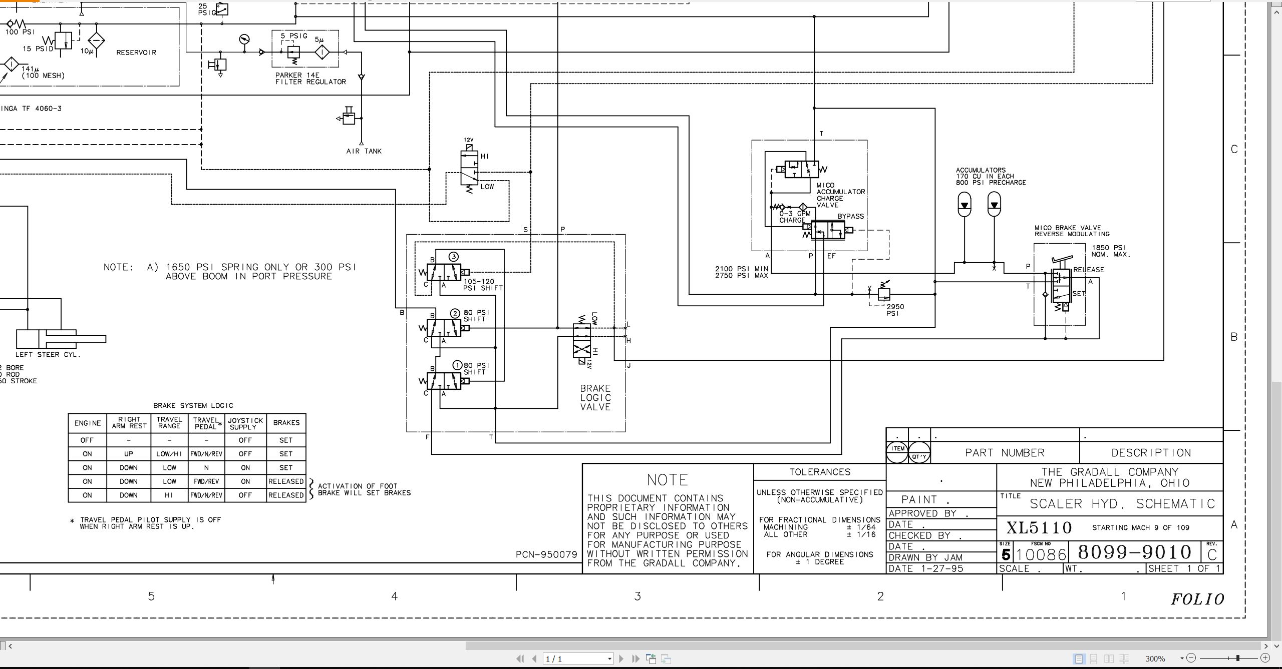
8099-9010 Hydraulic Schematic
RDE93010-02-R Rexroth Variable Displacement Pump Service Manual
RA64-774-S Rexroth Gear Pump Service Manual
RDE92002-30 Rexroth Variable Displacement Pump
RDE 91001-01-R Rexroth Swing Motor/Remote Drive Motor Service Manual
RA06735 Rexroth Applications & Service
RA64555 Rexroth Joystick
7-124 Char-Lynn Tilt Motor
81-460-091 Mico Hydraulic Brake Valve
MECHANICAL ADJUSTMENTS
29604 Upperstructure Mechanical Adjustments & Repair Manual
F74290 Ausco Swing Brake
S6A Fairfield Torque-Hub Service Manual
MISCELLANEOUS
29710 XL5000 Series Electrical Systems
STEERING
28902 Char-Lynn Troubleshooting
7-306 Char-Lynn Repair Information
STEERING AXLE
MM#2 Rockwell Front Non-Drive Steering Axles
TP-97117 Rockwell Maintenance Manual Update
DRIVE AXLE
MM#1 Rockwell Lubrication Manual
FMM#9 Planetary Axle Wheel Ends
S6C Fairfield Final Drive
T2A/JDT2A Fairfield Final Drive
BRAKE SYSTEM
MM#4 Rockwell Cam-Master Cam Brakes
WHEEL & RIM
0009 Rim & Wheel Safety Manual
XL5110 Operators Manual 2460-4146 2002.pdf (36 Pages)
XL5110 Combined Service Manual 2460-4147 2006.pdf (843 Pages)
Contents:
2460-4147 XL5110 COMBINED SERVICE MANUAL
OPERATOR INSTRUCTION
29701 Upperstructure Operation & Lube Manual
HYDRAULIC TESTING & ADJUSTMENT
29626 XL5110 Series Hydraulic System Manual
8099-9014 Scaler Hydraulic Schematic
RDE93010-02-R Rexroth Variable Displacement Pump Service Manual
RA64-774-S Rexroth Gear Pump Service Manual
RDE92002-30 Rexroth Swing Pump Service Manual
RDE 91001-01-R Rexroth Swing Motor/Remote Drive Motor Service Manual
RA06735 Rexroth Applications & Service
RA64555 Rexroth Joystick
MECHANICAL ADJUSTMENTS
29604 Upperstructure Mechanical Adjustments & Repair Manual
F74290 Ausco Swing Brake
S6A Fairfield Torque-Hub Service Manual
MISCELLANEOUS
29710 XL5000 Series Electrical Systems
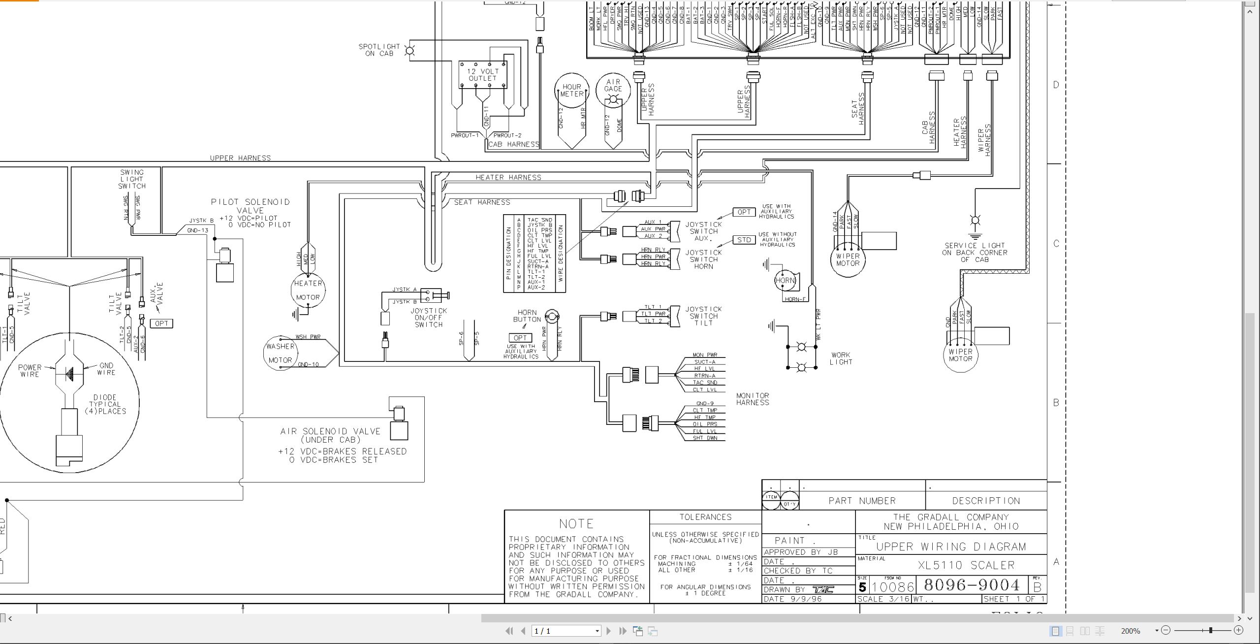
8096-9004 Upper Wiring Diagram
STEERING
28902 Char-Lynn Troubleshooting
7-306 Char-Lynn Repair Information
MM#2 Rockwell Front Non-Drive Steering Axles
TP-97117 Rockwell Maintenance Manual Update
DRIVE AXLE
MM#1 Rockwell Lubrication Manual
FMM#9 Planetary Axle Wheel Ends
S6C Fairfield Final Drive
T2A/JDT2A Fairfield Final Drive
BRAKE SYSTEM
MM#4 Rockwell Cam-Master Cam Brakes
BW5057 Bendix Air Brake Handbook
WHEEL & RIM
0009 Rim & Wheel Safety Manual
MISCELLANEOUS
8099-9013 Air Brake System Diagram
HE92-2 EMI Safety Manual
20013 Gradall Safety Manual
XL5110 EPA Parts Manual 31200017 2004.pdf (163 Pages)
Contents:
31200017 XL5110 PARTS MANUAL
UPPERSTRUCTURE
Section 1 Introduction
Section 2 Boom Assemblies
Section 3 Cab & Related Components
Section 4 Hydraulic System Components
Section 5 Main Hydraulic Systems
Section 6 Pilot Hydraulic Systems
Section 7 Attachments
UNDERCARRIAGE
Section 1 Introduction
Section 2 Undercarriage Assembly
Section 3 Steering Axle Assembly (Rear)
Section 4 Drive Axle Assembly (Front)
OPTIONS
XL5110 Parts Manual 31200085 2005.pdf (172 Pages)
Contents:
31200004 XL5110 PARTS MANUAL
UPPERSTRUCTURE
Section 1 Introduction
Section 2 Boom Assemblies
Section 3 Cab & Related Components
Section 4 Hydraulic System Components
Section 5 Main Hydraulic Systems
Section 6 Pilot Hydraulic Systems
Section 7 Attachments
UNDERCARRIAGE
Section 1 Introduction
Section 2 Undercarriage Assembly
Section 3 Steering Axle Assembly (Rear)
Section 4 Drive Axle Assembly (Front)
Section 5 Hydraulics
OPTIONS
XL5110 Parts Manual 31200091 2005.pdf (178 Pages)
Contents:
31200004 XL5110 PARTS MANUAL
UPPERSTRUCTURE
Section 1 Introduction
Section 2 Boom Assemblies
Section 3 Cab & Related Components
Section 4 Hydraulic System Components
Section 5 Main Hydraulic Systems
Section 6 Pilot Hydraulic Systems
Section 7 Attachments
UNDERCARRIAGE
Section 1 Introduction
Section 2 Undercarriage Assembly
Section 3 Steering Axle Assembly (Rear)
Section 4 Drive Axle Assembly (Front)
Section 5 Hydraulics
XL5110 Parts Manual 31200118 2005.pdf (172 Pages)
Contents:
31200118 XL5110 PARTS MANUAL
UPPERSTRUCTURE
Section 1 Introduction
Section 2 Boom Assemblies
Section 3 Cab & Related Components
Section 4 Hydraulic System Components
Section 5 Main Hydraulic Systems
Section 6 Pilot Hydraulic Systems
Section 7 Attachments
UNDERCARRIAGE
Section 1 Introduction
Section 2 Undercarriage Assembly
Section 3 Steering Axle Assembly (Rear)
Section 4 Drive Axle Assembly (Front)
Section 5 Hydraulics
XL5110 Parts Manual 31200157 2005.pdf (169 Pages)
Contents:
31200157 XL5110 PARTS MANUAL
UPPERSTRUCTURE
Section 1 Introduction
Section 2 Boom Assemblies
Section 3 Cab & Related Components
Section 4 Hydraulic System Components
Section 5 Main Hydraulic Systems
Section 6 Pilot Hydraulic Systems
Section 7 Attachments
UNDERCARRIAGE
Section 1 Introduction
Section 2 Undercarriage Assembly
Section 3 Steering Axle Assembly (Rear)
Section 4 Drive Axle Assembly (Front)
Section 5 Hydraulics
OPTIONS
XL5110 Illustrated Parts Manual 31200175 2005.pdf (278 Pages)
XL5110 Illustrated Parts Manual 31200212 2006.pdf (282 Pages)
Contents:
Service Kits
Section 1 Frame & Attaching Parts
Figure 1-1 Rotating Platform, L.H. View
Figure 1-2 Rotating Platform, R.H. View
Figure 1-3 Swing & Tilt Bearing, Cradle & Hoist Cylinder Mounting & Lube System
Section 2 Boom
Figure 2-1 Boom Cradle
Figure 2-2 Main Boom Assembly
Figure 2-3 Telescope Boom Assembly
Figure 2-4 Inside Hose Trough
Figure 2-5 Roller Bracket Assembly
Section 3 Attachments
Figure 3-1 Scaling Hook Installation
Section 4 Engine & Attaching Parts
Figure 4-1 Engine Assembly, L.H. View
Figure 4-2 Engine Assembly, R.H. View
Figure 4-3 Air Cleaner Installation
Figure 4-4 Air Cleaner Assembly
Figure 4-5 Exhaust System & Purifier
Figure 4-6 Fuel Tank & Lines
Figure 4-7 Oil Cooler, C.A.C., Radiator & Hoses
Figure 4-8 Filter Bracket Assembly
Figure 4-9 Oil Filter Assemblies
Figure 4-10 Pump Coupler Assembly
Figure 4-11 Upper Air System
Figure 4-12 Chassis Air System
Section 5 Drive Train
Figure 5-1 Frame & Miscellaneous Components
Figure 5-2 Steer Axle Assembly
Figure 5-3 Steer Axle Kit
Figure 5-4 Drive Axle Assembly
Figure 5-5 Drive Axle Kit
Figure 5-6 Planetary Gear Box Assembly
Section 6 Cab
Figure 6-1 Operators Cab
Figure 6-2 Cab Door
Figure 6-3 Cab Accoustical Liners & Window Glass
Figure 6-4 Cab Console
Figure 6-5 Cab Seat
Figure 6-6 Cab Heater & Installation
Section 7 Controls
Figure 7-1 Joystick Assembly
Figure 7-2 Steering Column
Figure 7-3 Foot Pedal Installation
Figure 7-4 Dual Brake Valve
Figure 7-5 Foot Pedal
Section 8 Hydraulic Circuits
Figure 8-1 Oil Supply to Pumps
Figure 8-2 Hydraulic Pressure to Control Valves
Figure 8-3 Hydraulic Hosing To Joysticks & Foot Operated Valves
Figure 8-4 Dump Circuit
Figure 8-5 Hoist Pilot
Figure 8-6 Boom Pilot
Figure 8-7 Tool Pilot
Figure 8-8 Propel Pilot
Figure 8-9 Hoist Cylinder
Figure 8-10 Boom Cylinder
Figure 8-11 Tool Cylinder
Figure 8-12 Swing & Swing Brake
Figure 8-13 Dual Swing Motor
Figure 8-14 Tilt Motor
Figure 8-15 Upper Propelling
Figure 8-16 Oil Filter & Hosing
Section 9 Hydraulic Components
Figure 9-1 Hoist Cylinder Assembly
Figure 9-2 Boom Cylinder Assembly
Figure 9-3 Tool Cylinder Assembly
Figure 9-4 Steering Cylinder Assembly
Figure 9-5 Main Pump – Front
Figure 9-6 Main Pump – Rear
Figure 9-7 Hoist, Tilt, Tool & Aux Control Valve Assembly
Figure 9-8 Hoist Valve Section Assembly
Figure 9-9 Tilt Valve Section Assembly
Figure 9-10 Tool Valve Section Assembly
Figure 9-11 Boom & Propel Control Valve Assembly
Figure 9-12 Propel Valve Section Assembly
Figure 9-13 Boom Valve Section Assembly
Figure 9-14 Reservoir Assembly
Figure 9-15 Swing Transmission Installation
Figure 9-16 Swing Transmission Assembly
Figure 9-17 Swing Motor Assembly
Figure 9-18 Swing Brake Assembly
Figure 9-19 Tilt Transmission Assembly
Figure 9-20 Tilt Brake Assembly
Figure 9-21 Tilt Motor Assembly
Figure 9-22 Center Pin Assembly
Figure 9-23 Oil Cooler Assembly
Figure 9-24 Steering Control Unit
Figure 9-25 Valve Assembly
Figure 9-26 Pilot/Steer Valve Assembly
Figure 9-27 Gear Pump Assembly
Figure 9-28 Thermal By-Pass Assembly
Figure 9-29 Pressure Reducing Valve Assembly
Figure 9-30 Pressure Reducing Valve
Figure 9-31 Swing Pump
Figure 9-32 Swing Pump
Figure 9-33 Swing Pump
Figure 9-34 Swing Pump
Figure 9-35 Steering Pump Assembly
Figure 9-36 Tilt Brake Release Valve Assembly
Figure 9-37 Piston Motor Assembly
Figure 9-38 Swing Brake Release Valve Assembly
Figure 9-39 Solenoid Valve Assembly
Figure 9-40 Clamp Sets & Miscellaneous Hydraulic Components
Section 10 Electrical
Figure 10-1 Batteries, VEC & Miscellaneous Electrical Components
Figure 10-2 Distribution Box
Section 11 Decals
Figure 11-1 Decals
Section 12 Options
Figure 12-1 Seat Belt Installation
Figure 12-2 Air Conditioner Kit
Figure 12-3 Condensor Installation
Figure 12-4 Air Conditioner Evaporator Kit
Figure 12-5 Cab Rock Guard Installation
Part Number Index
XL5110 Operators Manual 31200218 2006.pdf (36 Pages)
XL5110 Combined Service Manual 31200219 2006.pdf (862 Pages)
Contents:
31200219 XL5110 COMBINED SERVICE MANUAL
OPERATOR INSTRUCTION
31200218 XL5110 Operators Manual
HYDRAULIC TESTING & ADJUSTMENT
29626 XL5110 Series Hydraulic System Manual
8099-9014 Hydraulic Schematic
RDE93010-02-R Rexroth Variable Displacement Pump Service Manual
RA 10 097-5 Rexroth Gear Pump
RDE92002-30 Rexroth Swing Pump Service Manual
RDE 91001-01-R Rexroth Swing Motor/Remote Drive Motor Service Manual
RA06735 Rexroth Applications & Service
RA64555 Rexroth Joystick
MECHANICAL ADJUSTMENTS
29604 Upperstructure Mechanical Adjustments & Repair Manual
F74290 Ausco Swing Brake
S6A Fairfield Torque-Hub Service Manual
MISCELLANEOUS
29710 XL5000 Series Electrical Systems
S40 Electrical Schematic (S/N 0514152 thru 0511627)
906 Electrical Schematic (S/N 0511628 & After)
STEERING
28902 Char-Lynn Troubleshooting
7-306 Char-Lynn Repair Information
MM#2 Rockwell Front Non-Drive Steering Axles
TP-97117 Rockwell Maintenance Manual Update
DRIVE AXLE
MM#1 Rockwell Lubrication Manual
FMM#9 Planetary Axle Wheel Ends
S6C Fairfield Final Drive
T2A/JDT2A Fairfield Final Drive
BRAKE SYSTEM
MM#4 Rockwell Cam-Master Cam Brakes
BW5057 Bendix Air Brake Handbook
WHEEL & RIM
0009 Rim & Wheel Safety Manual
MISCELLANEOUS
8099-9013 Air Brake System Diagram
HE92-2 EMI Safety Manual
20013 Gradall Safety Manual
XL5110 Illustrated Parts Manual 31200232 2006.pdf (290 Pages)
Contents:
Service Kits
Section 1 FRAME & ATTACHING PARTS
Figure 1-1 Rotating Platform, L.H. View
Figure 1-2 Rotating Platform, R.H. View
Figure 1-3 Swing & Tilt Bearing, Cradle & Hoist Cylinder Mounting & Lube System
Section 2 Boom
Figure 2-1 Boom Cradle
Figure 2-2 Main Boom Assembly
Figure 2-3 Telescope Boom Assembly
Figure 2-4 Inside Hose Trough
Figure 2-5 Roller Bracket Assembly
Section 3 ATTACHmenTS
Figure 3-1 Scaling Hook Installation
Section 4 Engine & ATTACHING PARTS
Figure 4-1 Engine Assembly, L.H. View
Figure 4-2 Engine Assembly, R.H. View
Figure 4-3 Air Cleaner Installation
Figure 4-4 Air Cleaner Assembly
Figure 4-5 Exhaust System & Purifier
Figure 4-6 Fuel Tank & Lines
Figure 4-7 Oil Cooler, C.A.C., Radiator & Hoses
Figure 4-8 Filter Bracket Assembly
Figure 4-9 Oil Filter Assemblies
Figure 4-10 Pump Coupler Assembly
Figure 4-11 Upper Air System
Figure 4-12 Chassis Air System
Section 5 dRIVE tRAIN
Figure 5-1 Frame & Miscellaneous Components
Figure 5-2 Steer Axle Assembly
Figure 5-3 Steer Axle Kit
Figure 5-4 Drive Axle Assembly
Figure 5-5 Drive Axle Kit
Figure 5-6 Planetary Gear Box Assembly
Section 6 Cab
Figure 6-1 Operators Cab
Figure 6-2 Cab Door
Figure 6-3 Cab Accoustical Liners & Window Glass
Figure 6-4 Cab Console
Figure 6-5 Cab Seat
Figure 6-6 Cab Heater & Installation
Section 7 ControlS
Figure 7-1 Joystick Assembly
Figure 7-2 Steering Column
Figure 7-3 Foot Pedal Installation
Figure 7-4 Dual Brake Valve
Figure 7-5 Foot Pedal
Section 8 Hydraulic Circuits
Figure 8-1 Oil Supply to Pumps
Figure 8-2 Hydraulic Pressure to Control Valves
Figure 8-3 Hydraulic Hosing To Joysticks & Foot Operated Valves
Figure 8-4 Dump Circuit
Figure 8-5 Hoist Pilot
Figure 8-6 Boom Pilot
Figure 8-7 Tool Pilot
Figure 8-8 Propel Pilot
Figure 8-9 Hoist Cylinder
Figure 8-10 Boom Cylinder
Figure 8-11 Tool Cylinder
Figure 8-12 Swing & Swing Brake
Figure 8-13 Dual Swing Motor
Figure 8-14 Tilt Motor
Figure 8-15 Upper Propelling
Figure 8-16 Oil Filter & Hosing
Section 9 Hydraulic ComponenTS
Figure 9-1 Hoist Cylinder Assembly
Figure 9-2 Boom Cylinder Assembly
Figure 9-3 Tool Cylinder Assembly
Figure 9-4 Steering Cylinder Assembly
Figure 9-5 Main Pump – Front
Figure 9-6 Main Pump – Rear
Figure 9-7 Hoist, Tilt, Tool & Aux Control Valve Assembly
Figure 9-8 Hoist Valve Section Assembly
Figure 9-9 Tilt Valve Section Assembly
Figure 9-10 Tool Valve Section Assembly
Figure 9-11 Boom & Propel Control Valve Assembly
Figure 9-12 Propel Valve Section Assembly
Figure 9-13 Boom Valve Section Assembly
Figure 9-14 Reservoir Assembly
Figure 9-15 Swing Transmission Installation
Figure 9-16 Swing Transmission Assembly
Figure 9-17 Swing Motor Assembly
Figure 9-18 Swing Brake Assembly
Figure 9-19 Tilt Transmission Assembly
Figure 9-20 Tilt Brake Assembly
Figure 9-21 Tilt Motor Assembly
Figure 9-22 Center Pin Assembly
Figure 9-23 Oil Cooler Assembly
Figure 9-24 Steering Control Unit
Figure 9-25 Valve Assembly
Figure 9-26 Pilot/Steer Valve Assembly
Figure 9-27 Gear Pump Assembly
Figure 9-28 Thermal By-Pass Assembly
Figure 9-29 Pressure Reducing Valve Assembly
Figure 9-30 Pressure Reducing Valve
Figure 9-31 Swing Pump
Figure 9-32 Swing Pump
Figure 9-33 Swing Pump
Figure 9-34 Swing Pump
Figure 9-35 Steering Pump Assembly
Figure 9-36 Tilt Brake Release Valve Assembly
Figure 9-37 Piston Motor Assembly
Figure 9-38 Swing Brake Release Valve Assembly
Figure 9-39 Solenoid Valve Assembly
Figure 9-40 Clamp Sets & Miscellaneous Hydraulic Components
Section 10 Electrical
Figure 10-1 Batteries, VEC & Miscellaneous Electrical Components
Figure 10-2 Distribution Box
Section 11 Decals
Figure 11-1 Decals
Section 12 Options
Figure 12-1 Air Conditioner Kit
Figure 12-2 Condensor Installation
Figure 12-3 Air Conditioner Evaporator Kit
Figure 12-4 Cab Rock Guard Installation
Figure 12-5 Traction Lock Valve Installation
Figure 12-6 Traction Lock Valve
Figure 12-7 Boom Cover Access Panel Assy
Part Number Index
XL5110 Illustrated Parts Manual 31200244 2006.pdf (288 Pages)
Contents:
Service Kits
Section 1 Frame & Attaching Parts
Figure 1-1 Rotating Platform, L.H. View
Figure 1-2 Rotating Platform, R.H. View
Figure 1-3 Swing & Tilt Bearing, Cradle & Hoist Cylinder Mounting & Lube System
Section 2 Boom
Figure 2-1 Boom Cradle
Figure 2-2 Main Boom Assembly
Figure 2-3 Telescope Boom Assembly
Figure 2-4 Inside Hose Trough
Figure 2-5 Roller Bracket Assembly
Section 3 Attachments
Figure 3-1 Scaling Hook Installation
Section 4 Engine & Attaching Parts
Figure 4-1 Engine Assembly, L.H. View
Figure 4-2 Engine Assembly, R.H. View
Figure 4-3 Air Cleaner Installation
Figure 4-4 Air Cleaner Assembly
Figure 4-5 Exhaust System & Purifier
Figure 4-6 Fuel Tank & Lines
Figure 4-7 Oil Cooler, C.A.C., Radiator & Hoses
Figure 4-8 Filter Bracket Assembly
Figure 4-9 Oil Filter Assemblies
Figure 4-10 Pump Coupler Assembly
Figure 4-11 Upper Air System
Figure 4-12 Chassis Air System
Section 5 Drive Train
Figure 5-1 Frame & Miscellaneous Components
Figure 5-2 Steer Axle Assembly
Figure 5-3 Steer Axle Kit
Figure 5-4 Drive Axle Assembly
Figure 5-5 Drive Axle Kit
Figure 5-6 Planetary Gear Box Assembly
Section 6 Cab
Figure 6-1 Operators Cab
Figure 6-2 Cab Door
Figure 6-3 Cab Accoustical Liners & Window Glass
Figure 6-4 Cab Console
Figure 6-5 Cab Seat
Figure 6-6 Cab Heater & Installation
Section 7 Controls
Figure 7-1 Joystick Assembly
Figure 7-2 Steering Column
Figure 7-3 Foot Pedal Installation
Figure 7-4 Dual Brake Valve
Figure 7-5 Foot Pedal
Section 8 Hydraulic Circuits
Figure 8-1 Oil Supply to Pumps
Figure 8-2 Hydraulic Pressure to Control Valves
Figure 8-3 Hydraulic Hosing To Joysticks & Foot Operated Valves
Figure 8-4 Dump Circuit
Figure 8-5 Hoist Pilot
Figure 8-6 Boom Pilot
Figure 8-7 Tool Pilot
Figure 8-8 Propel Pilot
Figure 8-9 Hoist Cylinder
Figure 8-10 Boom Cylinder
Figure 8-11 Tool Cylinder
Figure 8-12 Swing & Swing Brake
Figure 8-13 Dual Swing Motor
Figure 8-14 Tilt Motor
Figure 8-15 Upper Propelling
Figure 8-16 Oil Filter & Hosing
Section 9 Hydraulic Components
Figure 9-1 Hoist Cylinder Assembly
Figure 9-2 Boom Cylinder Assembly
Figure 9-3 Tool Cylinder Assembly
Figure 9-4 Steering Cylinder Assembly
Figure 9-5 Main Pump – Front
Figure 9-6 Main Pump – Rear
Figure 9-7 Hoist, Tilt, Tool & Aux Control Valve Assembly
Figure 9-8 Hoist Valve Section Assembly
Figure 9-9 Tilt Valve Section Assembly
Figure 9-10 Tool Valve Section Assembly
Figure 9-11 Boom & Propel Control Valve Assembly
Figure 9-12 Propel Valve Section Assembly
Figure 9-13 Boom Valve Section Assembly
Figure 9-14 Reservoir Assembly
Figure 9-15 Swing Transmission Installation
Figure 9-16 Swing Transmission Assembly
Figure 9-17 Swing Motor Assembly
Figure 9-18 Swing Brake Assembly
Figure 9-19 Tilt Transmission Assembly
Figure 9-20 Tilt Brake Assembly
Figure 9-21 Tilt Motor Assembly
Figure 9-22 Center Pin Assembly
Figure 9-23 Oil Cooler Assembly
Figure 9-24 Steering Control Unit
Figure 9-25 Valve Assembly
Figure 9-26 Pilot/Steer Valve Assembly
Figure 9-27 Gear Pump Assembly
Figure 9-28 Thermal By-Pass Assembly
Figure 9-29 Pressure Reducing Valve Assembly
Figure 9-30 Pressure Reducing Valve
Figure 9-31 Swing Pump
Figure 9-32 Swing Pump
Figure 9-33 Swing Pump
Figure 9-34 Swing Pump
Figure 9-35 Steering Pump Assembly
Figure 9-36 Tilt Brake Release Valve Assembly
Figure 9-37 Piston Motor Assembly
Figure 9-38 Swing Brake Release Valve Assembly
Figure 9-39 Solenoid Valve Assembly
Figure 9-40 Clamp Sets & Miscellaneous Hydraulic Components
Section 10 Electrical
Figure 10-1 Batteries, VEC & Miscellaneous Electrical Components
Figure 10-2 Distribution Box
Section 11 Decals
Figure 11-1 Decals
Section 12 Options
Figure 12-1 Seat Belt Installation
Figure 12-2 Air Conditioner Kit
Figure 12-3 Condensor Installation
Figure 12-4 Air Conditioner Evaporator Kit
Figure 12-5 Cab Rock Guard Installation
Figure 12-6 Traction Lock Valve Installation
Figure 12-7 Traction Lock Valve
Part Number Index
XL5110 Illustrated Parts Manual 31200263 2006.pdf (292 Pages)
Contents:
Service Kits
Section 1 Frame & Attaching Parts
Figure 1-1 Rotating Platform, L.H. View
Figure 1-2 Rotating Platform, R.H. View
Figure 1-3 Swing & Tilt Bearing, Cradle & Hoist Cylinder Mounting & Lube System
Section 2 Boom
Figure 2-1 Boom Cradle
Figure 2-2 Main Boom Assembly
Figure 2-3 Telescope Boom Assembly
Figure 2-4 Roller Bracket Assembly
Section 3 Attachments
Figure 3-1 Scaling Hook Installation
Section 4 Engine & Attaching Parts
Figure 4-1 Engine Assembly, L.H. View
Figure 4-2 Engine Assembly, R.H. View
Figure 4-3 Air Cleaner Installation
Figure 4-4 Air Cleaner Assembly
Figure 4-5 Exhaust System & Purifier
Figure 4-6 Fuel Tank & Lines
Figure 4-7 Oil Cooler, C.A.C., Radiator & Hoses
Figure 4-8 Filter Bracket Assembly
Figure 4-9 Oil Filter Assemblies
Figure 4-10 Pump Coupler Assembly
Figure 4-11 Upper Air System
Figure 4-12 Chassis Air System
Section 5 Drive Train
Figure 5-1 Frame & Miscellaneous Components
Figure 5-2 Steer Axle Assembly
Figure 5-3 Steer Axle Kit
Figure 5-4 Drive Axle Assembly
Figure 5-5 Drive Axle Kit
Figure 5-6 Planetary Gear Box Assembly
Section 6 Cab
Figure 6-1 Operators Cab
Figure 6-2 Cab Door
Figure 6-3 Cab Accoustical Liners & Window Glass
Figure 6-4 Cab Console
Figure 6-5 Cab Seat
Figure 6-6 Cab Heater & Installation
Section 7 Controls
Figure 7-1 Joystick Assembly
Figure 7-2 Steering Column
Figure 7-3 Foot Pedal Installation
Figure 7-4 Dual Brake Valve
Figure 7-5 Foot Pedal
Section 8 Hydraulic Circuits
Figure 8-1 Oil Supply to Pumps
Figure 8-2 Hydraulic Pressure to Control Valves
Figure 8-3 Hydraulic Hosing To Joysticks & Foot Operated Valves
Figure 8-4 Dump Circuit
Figure 8-5 Hoist Pilot
Figure 8-6 Boom Pilot
Figure 8-7 Tool Pilot
Figure 8-8 Propel Pilot
Figure 8-9 Hoist Cylinder
Figure 8-10 Boom Cylinder
Figure 8-11 Tool Cylinder
Figure 8-12 Swing & Swing Brake
Figure 8-13 Dual Swing Motor
Figure 8-14 Tilt Motor
Figure 8-15 Upper Propelling
Figure 8-16 Oil Filter & Hosing
Section 9 Hydraulic Components
Figure 9-1 Hoist Cylinder Assembly
Figure 9-2 Boom Cylinder Assembly
Figure 9-3 Tool Cylinder Assembly
Figure 9-4 Steering Cylinder Assembly
Figure 9-5 Main Pump – Front
Figure 9-6 Main Pump – Rear
Figure 9-7 Hoist, Tilt, Tool & Aux Control Valve Assembly
Figure 9-8 Hoist Valve Section Assembly
Figure 9-9 Tilt Valve Section Assembly
Figure 9-10 Tool Valve Section Assembly
Figure 9-11 Boom & Propel Control Valve Assembly
Figure 9-12 Propel Valve Section Assembly
Figure 9-13 Boom Valve Section Assembly
Figure 9-14 Reservoir Assembly
Figure 9-15 Swing Transmission Installation
Figure 9-16 Swing Transmission Assembly
Figure 9-17 Swing Motor Assembly
Figure 9-18 Swing Brake Assembly
Figure 9-19 Tilt Transmission Assembly
Figure 9-20 Tilt Brake Assembly
Figure 9-21 Tilt Motor Assembly
Figure 9-22 Center Pin Assembly
Figure 9-23 Oil Cooler Assembly
Figure 9-24 Steering Control Unit
Figure 9-25 Valve Assembly
Figure 9-26 Pilot/Steer Valve Assembly
Figure 9-27 Gear Pump Assembly
Figure 9-28 Thermal By-Pass Assembly
Figure 9-29 Pressure Reducing Valve Assembly
Figure 9-30 Pressure Reducing Valve
Figure 9-31 Swing Pump
Figure 9-32 Swing Pump
Figure 9-33 Swing Pump
Figure 9-34 Swing Pump
Figure 9-35 Steering Pump Assembly
Figure 9-36 Tilt Brake Release Valve Assembly
Figure 9-37 Piston Motor Assembly
Figure 9-38 Swing Brake Release Valve Assembly
Figure 9-39 Solenoid Valve Assembly
Figure 9-40 Clamp Sets & Miscellaneous Hydraulic Components
Section 10 Electrical
Figure 10-1 Batteries, VEC & Miscellaneous Electrical Components
Figure 10-2 Distribution Box
Section 11 Decals
Figure 11-1 Decals
Section 12 Options
Figure 12-1 Air Conditioner Kit
Figure 12-2 Condensor Installation
Figure 12-3 External Air Conditioning Filter Installation
Figure 12-4 Air Conditioner Evaporator Kit
Figure 12-5 Cab Rock Guard Installation
Figure 12-6 Traction Lock Valve Installation
Figure 12-7 Traction Lock Valve
Figure 12-8 Boom Cover Access Panel Assy
Figure 12-9 Floodlight Installation
Part Number Index
XL5110 Illustrated Parts Manual 31200272 2006.pdf (298 Pages)
Contents:
Service Kits
Section 1 Frame & Attaching Parts
Figure 1-1 Rotating Platform, L.H. View
Figure 1-2 Rotating Platform, R.H. View
Figure 1-3 Swing & Tilt Bearing, Cradle & Hoist Cylinder Mounting & Lube System
Section 2 Boom
Figure 2-1 Boom Cradle
Figure 2-2 Main Boom Assembly
Figure 2-3 Telescope Boom Assembly
Figure 2-4 Roller Bracket Assembly
Figure 2-5 360 Degree Tilt Gland Assembly
Section 3 Attachments
Figure 3-1 Scaling Hook Installation
Section 4 Engine & Attaching Parts
Figure 4-1 Engine Assembly, L.H. View
Figure 4-2 Engine Assembly, R.H. View
Figure 4-3 Air Cleaner Installation
Figure 4-4 Air Cleaner Assembly
Figure 4-5 Exhaust System & Purifier
Figure 4-6 Fuel Tank & Lines
Figure 4-7 Oil Cooler, C.A.C., Radiator & Hoses
Figure 4-8 Filter Bracket Assembly
Figure 4-9 Oil Filter Assemblies
Figure 4-10 Pump Coupler Assembly
Figure 4-11 Upper Air System
Figure 4-12 Chassis Air System
Section 5 Drive Train
Figure 5-1 Frame & Miscellaneous Components
Figure 5-2 Steer Axle Assembly
Figure 5-3 Steer Axle Kit
Figure 5-4 Drive Axle Assembly
Figure 5-5 Drive Axle Kit
Figure 5-6 Planetary Gear Box Assembly
Section 6 Cab
Figure 6-1 Operators Cab
Figure 6-2 Cab Door
Figure 6-3 Cab Accoustical Liners & Window Glass
Figure 6-4 Cab Console
Figure 6-5 Cab Seat
Figure 6-6 Cab Heater & Installation
Section 7 Controls
Figure 7-1 Joystick Assembly
Figure 7-2 Steering Column
Figure 7-3 Foot Pedal Installation
Figure 7-4 Dual Brake Valve
Figure 7-5 Foot Pedal
Section 8 Hydraulic Circuits
Figure 8-1 Oil Supply to Pumps
Figure 8-2 Hydraulic Pressure to Control Valves
Figure 8-3 Hydraulic Hosing To Joysticks & Foot Operated Valves
Figure 8-4 Dump Circuit
Figure 8-5 Hoist Pilot
Figure 8-6 Boom Pilot
Figure 8-7 Tool Pilot
Figure 8-8 Propel Pilot
Figure 8-9 Hoist Cylinder
Figure 8-10 Boom Cylinder
Figure 8-11 Tool Cylinder
Figure 8-12 Swing & Swing Brake
Figure 8-13 Dual Swing Motor
Figure 8-14 Tilt Motor
Figure 8-15 Upper Propelling
Figure 8-16 Oil Filter & Hosing
Section 9 Hydraulic Components
Figure 9-1 Hoist Cylinder Assembly
Figure 9-2 Boom Cylinder Assembly
Figure 9-3 Tool Cylinder Assembly
Figure 9-4 Steering Cylinder Assembly
Figure 9-5 Main Pump – Front
Figure 9-6 Main Pump – Rear
Figure 9-7 Hoist, Tilt, Tool & Aux Control Valve Assembly
Figure 9-8 Hoist Valve Section Assembly
Figure 9-9 Tilt Valve Section Assembly
Figure 9-10 Tool Valve Section Assembly
Figure 9-11 Boom & Propel Control Valve Assembly
Figure 9-12 Propel Valve Section Assembly
Figure 9-13 Boom Valve Section Assembly
Figure 9-14 Reservoir Assembly
Figure 9-15 Swing Transmission Installation
Figure 9-16 Swing Transmission Assembly
Figure 9-17 Swing Motor Assembly
Figure 9-18 Swing Brake Assembly
Figure 9-19 Tilt Transmission Assembly
Figure 9-20 Tilt Brake Assembly
Figure 9-21 Tilt Motor Assembly
Figure 9-22 Center Pin Assembly
Figure 9-23 Oil Cooler Assembly
Figure 9-24 Steering Control Unit
Figure 9-25 Valve Assembly
Figure 9-26 Pilot/Steer Valve Assembly
Figure 9-27 Gear Pump Assembly
Figure 9-28 Thermal By-Pass Assembly
Figure 9-29 Pressure Reducing Valve Assembly
Figure 9-30 Pressure Reducing Valve
Figure 9-31 Swing Pump
Figure 9-32 Swing Pump
Figure 9-33 Swing Pump
Figure 9-34 Swing Pump
Figure 9-35 Steering Pump Assembly
Figure 9-36 Tilt Brake Release Valve Assembly
Figure 9-37 Piston Motor Assembly
Figure 9-38 Swing Brake Release Valve Assembly
Figure 9-39 Solenoid Valve Assembly
Figure 9-40 Clamp Sets & Miscellaneous Hydraulic Components
Figure 9-41 Blade Tilt Cylinder
Figure 9-42 Blade Diverter Valve
Section 10 Electrical
Figure 10-1 Batteries, VEC & Miscellaneous Electrical Components
Figure 10-2 Distribution Box
Section 11 Decals
Figure 11-1 Decals
Section 12 Options
Figure 12-1 Air Conditioner Kit
Figure 12-2 Condensor Installation
Figure 12-3 Air Conditioner Evaporator Kit
Figure 12-4 Blade Installation #1
Figure 12-5 Blade Installation #2
Figure 12-6 Blade Installation #3
Figure 12-7 Blade Installation #4
Figure 12-8 Lift Arrangement Components
Part Number Index
XL5110 Illustrated Parts Manual 31200290 2009.pdf (292 Pages)
Contents:
Service Kits
Section 1 Frame & Attaching Parts
Figure 1-1 Rotating Platform, L.H. View
Figure 1-2 Rotating Platform, R.H. View
Figure 1-3 Swing & Tilt Bearing, Cradle & Hoist Cylinder Mounting & Lube System
Section 2 Boom
Figure 2-1 Boom Cradle
Figure 2-2 Main Boom Assembly
Figure 2-3 Telescope Boom Assembly
Figure 2-4 Inside Hose Trough
Figure 2-5 Roller Bracket Assembly
Section 3 Attachments
Figure 3-1 Scaling Hook Installation
Section 4 Engine & Attaching Parts
Figure 4-1 Engine Assembly, L.H. View
Figure 4-2 Engine Assembly, R.H. View
Figure 4-3 Air Cleaner Installation
Figure 4-4 Air Cleaner Assembly
Figure 4-5 Exhaust System & Purifier
Figure 4-6 Fuel Tank & Lines
Figure 4-7 Oil Cooler, C.A.C., Radiator & Hoses
Figure 4-8 Filter Bracket Assembly
Figure 4-9 Oil Filter Assemblies
Figure 4-10 Pump Coupler Assembly
Figure 4-11 Upper Air System
Figure 4-12 Chassis Air System
Section 5 Drive Train
Figure 5-1 Frame & Miscellaneous Components
Figure 5-2 Steer Axle Assembly
Figure 5-3 Steer Axle Kit
Figure 5-4 Drive Axle Assembly
Figure 5-5 Drive Axle Kit
Figure 5-6 Planetary Gear Box Assembly
Section 6 Cab
Figure 6-1 Operators Cab
Figure 6-2 Cab Door
Figure 6-3 Cab Accoustical Liners & Window Glass
Figure 6-4 Cab Console
Figure 6-5 Cab Seat
Section 7 Controls
Figure 7-1 Joystick Assembly
Figure 7-2 Steering Column
Figure 7-3 Foot Pedal Installation
Figure 7-4 Dual Brake Valve
Figure 7-5 Foot Pedal
Section 8 Hydraulic Circuits
Figure 8-1 Oil Supply to Pumps
Figure 8-2 Hydraulic Pressure to Control Valves
Figure 8-3 Hydraulic Hosing To Joysticks & Foot Operated Valves
Figure 8-4 Dump Circuit
Figure 8-5 Hoist Pilot
Figure 8-6 Boom Pilot
Figure 8-7 Tool Pilot
Figure 8-8 Propel Pilot
Figure 8-9 Hoist Cylinder
Figure 8-10 Boom Cylinder
Figure 8-11 Tool Cylinder
Figure 8-12 Swing & Swing Brake
Figure 8-13 Dual Swing Motor
Figure 8-14 Tilt Motor
Figure 8-15 Upper Propelling
Figure 8-16 Oil Filter & Hosing
Section 9 Hydraulic Components
Figure 9-1 Hoist Cylinder Assembly
Figure 9-2 Boom Cylinder Assembly
Figure 9-3 Tool Cylinder Assembly
Figure 9-4 Steering Cylinder Assembly
Figure 9-5 Main Pump – Front
Figure 9-6 Main Pump – Rear
Figure 9-7 Hoist, Tilt, Tool & Aux Control Valve Assembly
Figure 9-8 Hoist Valve Section Assembly
Figure 9-9 Tilt Valve Section Assembly
Figure 9-10 Tool Valve Section Assembly
Figure 9-11 Boom & Propel Control Valve Assembly
Figure 9-12 Propel Valve Section Assembly
Figure 9-13 Boom Valve Section Assembly
Figure 9-14 Reservoir Assembly
Figure 9-15 Swing Transmission Installation
Figure 9-16 Swing Transmission Assembly
Figure 9-17 Swing Motor Assembly
Figure 9-18 Swing Brake Assembly
Figure 9-19 Tilt Transmission Assembly
Figure 9-20 Tilt Brake Assembly
Figure 9-21 Tilt Motor Assembly
Figure 9-22 Center Pin Assembly
Figure 9-23 Oil Cooler Assembly
Figure 9-24 Steering Control Unit
Figure 9-25 Valve Assembly
Figure 9-26 Pilot/Steer Valve Assembly
Figure 9-27 Gear Pump Assembly
Figure 9-28 Thermal By-Pass Assembly
Figure 9-29 Pressure Reducing Valve Assembly
Figure 9-30 Pressure Reducing Valve
Figure 9-31 Swing Pump
Figure 9-32 Swing Pump
Figure 9-33 Swing Pump
Figure 9-34 Swing Pump
Figure 9-35 Steering Pump Assembly
Figure 9-36 Tilt Brake Release Valve Assembly
Figure 9-37 Piston Motor Assembly
Figure 9-38 Swing Brake Release Valve Assembly
Figure 9-39 Solenoid Valve Assembly
Figure 9-40 Clamp Sets & Miscellaneous Hydraulic Components
Section 10 Electrical
Figure 10-1 Batteries, VEC, Battery Disconnect Switch & Miscellaneous Electrical Components
Figure 10-2 Distribution Box
Section 11 Decals
Figure 11-1 Decals
Section 12 Options
Figure 12-1 Air Conditioner Kit
Figure 12-2 Condensor Installation
Figure 12-3 External Air Conditioning Filter Installation
Figure 12-4 Cab Rock Guard Installation
Figure 12-5 Traction Lock Valve Installation
Figure 12-6 Traction Lock Valve
Figure 12-7 Floodlight Installation
Figure 12-8 Fire Extinguisher Installation
Figure 12-9 Walkway Installation
Part Number Index
XL5110 Illustrated Parts Manual 31200298 2007.pdf (292 Pages)
Contents:
Service Kits
Section 1 Frame & Attaching Parts
Figure 1-1 Rotating Platform, L.H. View
Figure 1-2 Rotating Platform, R.H. View
Figure 1-3 Swing & Tilt Bearing, Cradle & Hoist Cylinder Mounting & Lube System
Section 2 Boom
Figure 2-1 Boom Cradle
Figure 2-2 Main Boom Assembly
Figure 2-3 Telescope Boom Assembly
Figure 2-4 Inside Hose Trough
Figure 2-5 Roller Bracket Assembly
Section 3 Attachments
Figure 3-1 Scaling Hook Installation
Section 4 Engine & Attaching Parts
Figure 4-1 Engine Assembly, L.H. View
Figure 4-2 Engine Assembly, R.H. View
Figure 4-3 Air Cleaner Installation
Figure 4-4 Air Cleaner Assembly
Figure 4-5 Exhaust System & Purifier
Figure 4-6 Fuel Tank & Lines
Figure 4-7 Oil Cooler, C.A.C., Radiator & Hoses
Figure 4-8 Filter Bracket Assembly
Figure 4-9 Oil Filter Assemblies
Figure 4-10 Pump Coupler Assembly
Figure 4-11 Upper Air System
Figure 4-12 Chassis Air System
Section 5 Drive Train
Figure 5-1 Frame & Miscellaneous Components
Figure 5-2 Steer Axle Assembly
Figure 5-3 Steer Axle Kit
Figure 5-4 Drive Axle Assembly
Figure 5-5 Drive Axle Kit
Figure 5-6 Planetary Gear Box Assembly
Section 6 Cab
Figure 6-1 Operators Cab
Figure 6-2 Cab Door
Figure 6-3 Cab Accoustical Liners & Window Glass
Figure 6-4 Cab Console
Figure 6-5 Cab Seat
Figure 6-6 Cab Heater & Installation
Section 7 Controls
Figure 7-1 Joystick Assembly
Figure 7-2 Steering Column
Figure 7-3 Foot Pedal Installation
Figure 7-4 Dual Brake Valve
Figure 7-5 Foot Pedal
Section 8 Hydraulic Circuits
Figure 8-1 Oil Supply to Pumps
Figure 8-2 Hydraulic Pressure to Control Valves
Figure 8-3 Hydraulic Hosing To Joysticks & Foot Operated Valves
Figure 8-4 Dump Circuit
Figure 8-5 Hoist Pilot
Figure 8-6 Boom Pilot
Figure 8-7 Tool Pilot
Figure 8-8 Propel Pilot
Figure 8-9 Hoist Cylinder
Figure 8-10 Boom Cylinder
Figure 8-11 Tool Cylinder
Figure 8-12 Swing & Swing Brake
Figure 8-13 Dual Swing Motor
Figure 8-14 Tilt Motor
Figure 8-15 Upper Propelling
Figure 8-16 Oil Filter & Hosing
Section 9 Hydraulic Components
Figure 9-1 Hoist Cylinder Assembly
Figure 9-2 Boom Cylinder Assembly
Figure 9-3 Tool Cylinder Assembly
Figure 9-4 Steering Cylinder Assembly
Figure 9-5 Main Pump – Front
Figure 9-6 Main Pump – Rear
Figure 9-7 Hoist, Tilt, Tool & Aux Control Valve Assembly
Figure 9-8 Hoist Valve Section Assembly
Figure 9-9 Tilt Valve Section Assembly
Figure 9-10 Tool Valve Section Assembly
Figure 9-11 Boom & Propel Control Valve Assembly
Figure 9-12 Propel Valve Section Assembly
Figure 9-13 Boom Valve Section Assembly
Figure 9-14 Reservoir Assembly
Figure 9-15 Swing Transmission Installation
Figure 9-16 Swing Transmission Assembly
Figure 9-17 Swing Motor Assembly
Figure 9-18 Swing Brake Assembly
Figure 9-19 Tilt Transmission Assembly
Figure 9-20 Tilt Brake Assembly
Figure 9-21 Tilt Motor Assembly
Figure 9-22 Center Pin Assembly
Figure 9-23 Oil Cooler Assembly
Figure 9-24 Steering Control Unit
Figure 9-25 Valve Assembly
Figure 9-26 Pilot/Steer Valve Assembly
Figure 9-27 Gear Pump Assembly
Figure 9-28 Thermal By-Pass Assembly
Figure 9-29 Pressure Reducing Valve Assembly
Figure 9-30 Pressure Reducing Valve
Figure 9-31 Swing Pump
Figure 9-32 Swing Pump
Figure 9-33 Swing Pump
Figure 9-34 Swing Pump
Figure 9-35 Steering Pump Assembly
Figure 9-36 Tilt Brake Release Valve Assembly
Figure 9-37 Piston Motor Assembly
Figure 9-38 Swing Brake Release Valve Assembly
Figure 9-39 Solenoid Valve Assembly
Figure 9-40 Clamp Sets & Miscellaneous Hydraulic Components
Section 10 Electrical
Figure 10-1 Batteries, VEC & Miscellaneous Electrical Components
Figure 10-2 Distribution Box
Section 11 Decals
Figure 11-1 Decals
Section 12 Options
Figure 12-1 Air Conditioner Kit
Figure 12-2 Condensor Installation
Figure 12-3 External Air Conditioning Filter Installation
Figure 12-4 Air Conditioner Evaporator Kit
Figure 12-5 Cab Rock Guard Installation
Figure 12-6 Traction Lock Valve Installation
Figure 12-7 Traction Lock Valve
Figure 12-8 Floodlight Installation
Part Number Index
XL5110 Illustrated Parts Manual 31200304 2007.pdf (300 Pages)
Contents:
Service Kits
Section 1 Frame & Attaching Parts
Figure 1-1 Rotating Platform, L.H. View
Figure 1-2 Rotating Platform, R.H. View
Figure 1-3 Swing & Tilt Bearing, Cradle & Hoist Cylinder Mounting & Lube System
Section 2 Boom
Figure 2-1 Boom Cradle
Figure 2-2 Main Boom Assembly
Figure 2-3 Telescope Boom Assembly
Figure 2-4 Inside Hose Trough
Figure 2-5 Roller Bracket Assembly
Figure 2-6 4-Line Hose Trough Installation Components
Section 3 Attachments
Figure 3-1 Hammer Bracket Installation
Section 4 Engine & Attaching Parts
Figure 4-1 Engine Assembly, L.H. View
Figure 4-2 Engine Assembly, R.H. View
Figure 4-3 Air Cleaner Installation
Figure 4-4 Air Cleaner Assembly
Figure 4-5 Exhaust System & Purifier
Figure 4-6 Fuel Tank & Lines
Figure 4-7 Oil Cooler, C.A.C., Radiator & Hoses
Figure 4-8 Filter Bracket Assembly
Figure 4-9 Oil Filter Assemblies
Figure 4-10 Pump Coupler Assembly
Figure 4-11 Upper Air System
Figure 4-12 Chassis Air System
Section 5 Drive Train
Figure 5-1 Frame & Miscellaneous Components
Figure 5-2 Steer Axle Assembly
Figure 5-3 Steer Axle Kit
Figure 5-4 Drive Axle Assembly
Figure 5-5 Drive Axle Kit
Figure 5-6 Planetary Gear Box Assembly
Section 6 Cab
Figure 6-1 Operators Cab
Figure 6-2 Cab Door
Figure 6-3 Cab Accoustical Liners & Window Glass
Figure 6-4 Cab Console
Figure 6-5 Cab Seat
Figure 6-6 Cab Heater & Installation
Section 7 Controls
Figure 7-1 Joystick Assembly
Figure 7-2 Steering Column
Figure 7-3 Foot Pedal Installation
Figure 7-4 Dual Brake Valve
Figure 7-5 Foot Pedal
Section 8 Hydraulic Circuits
Figure 8-1 Oil Supply to Pumps
Figure 8-2 Hydraulic Pressure to Control Valves
Figure 8-3 Hydraulic Hosing To Joysticks & Foot Operated Valves
Figure 8-4 Dump Circuit
Figure 8-5 Hoist Pilot
Figure 8-6 Boom Pilot
Figure 8-7 Tool Pilot
Figure 8-8 Propel Pilot
Figure 8-9 Hoist Cylinder
Figure 8-10 Boom Cylinder
Figure 8-11 Tool Cylinder
Figure 8-12 Swing & Swing Brake
Figure 8-13 Dual Swing Motor
Figure 8-14 Tilt Motor
Figure 8-15 Upper Propelling
Figure 8-16 Oil Filter & Hosing
Section 9 Hydraulic Components
Figure 9-1 Hoist Cylinder Assembly
Figure 9-2 Boom Cylinder Assembly
Figure 9-3 Tool Cylinder Assembly
Figure 9-4 Steering Cylinder Assembly
Figure 9-5 Main Pump – Front
Figure 9-6 Main Pump – Rear
Figure 9-7 Hoist, Tilt, Tool & Aux Control Valve Assembly
Figure 9-8 Hoist Valve Section Assembly
Figure 9-9 Tilt Valve Section Assembly
Figure 9-10 Tool Valve Section Assembly
Figure 9-11 Boom & Propel Control Valve Assembly
Figure 9-12 Propel Valve Section Assembly
Figure 9-13 Boom Valve Section Assembly
Figure 9-14 Reservoir Assembly
Figure 9-15 Swing Transmission Installation
Figure 9-16 Swing Transmission Assembly
Figure 9-17 Swing Motor Assembly
Figure 9-18 Swing Brake Assembly
Figure 9-19 Tilt Transmission Assembly
Figure 9-20 Tilt Brake Assembly
Figure 9-21 Tilt Motor Assembly
Figure 9-22 Center Pin Assembly
Figure 9-23 Oil Cooler Assembly
Figure 9-24 Steering Control Unit
Figure 9-25 Valve Assembly
Figure 9-26 Pilot/Steer Valve Assembly
Figure 9-27 Gear Pump Assembly
Figure 9-28 Thermal By-Pass Assembly
Figure 9-29 Pressure Reducing Valve Assembly
Figure 9-30 Pressure Reducing Valve
Figure 9-31 Swing Pump
Figure 9-32 Swing Pump
Figure 9-33 Swing Pump
Figure 9-34 Swing Pump
Figure 9-35 Steering Pump Assembly
Figure 9-36 Tilt Brake Release Valve Assembly
Figure 9-37 Piston Motor Assembly
Figure 9-38 Swing Brake Release Valve Assembly
Figure 9-39 Solenoid Valve Assembly
Figure 9-40 Clamp Sets & Miscellaneous Hydraulic Components
Figure 9-41 Auxiliary Valve Section Assembly
Section 10 Electrical
Figure 10-1 Batteries, VEC & Miscellaneous Electrical Components
Figure 10-2 Distribution Box
Section 11 Decals
Figure 11-1 Decals
Section 12 Options
Figure 12-1 Air Conditioner Kit
Figure 12-2 Condensor Installation
Figure 12-3 External Air Conditioning Filter Installation
Figure 12-4 Air Conditioner Evaporator Kit
Figure 12-5 Cab Rock Guard Installation
Figure 12-6 Traction Lock Valve Installation
Figure 12-7 Traction Lock Valve
Figure 12-8 Boom Cover Access Panel Assy
Figure 12-9 Floodlight Installation
Figure 12-10 Travel Motor Case Drain Hose Upgrade
Part Number Index
XL5110 Illustrated Parts Manual 31200309 2007.pdf (298 Pages)
Contents:
Service Kits
Section 1 Frame & Attaching Parts
Figure 1-1 Rotating Platform, L.H. View
Figure 1-2 Rotating Platform, R.H. View
Figure 1-3 Swing & Tilt Bearing, Cradle & Hoist Cylinder Mounting & Lube System
Section 2 Boom
Figure 2-1 Boom Cradle
Figure 2-2 Main Boom Assembly
Figure 2-3 Telescope Boom Assembly
Figure 2-4 Inside Hose Trough
Figure 2-5 Roller Bracket Assembly
Figure 2-6 4-Line Hose Trough Installation Components
Section 3 Attachments
Figure 3-1 Scaling Hook Installation
Section 4 Engine & Attaching Parts
Figure 4-1 Engine Assembly, L.H. View
Figure 4-2 Engine Assembly, R.H. View
Figure 4-3 Air Cleaner Installation
Figure 4-4 Air Cleaner Assembly
Figure 4-5 Exhaust System & Purifier
Figure 4-6 Fuel Tank & Lines
Figure 4-7 Oil Cooler, C.A.C., Radiator & Hoses
Figure 4-8 Filter Bracket Assembly
Figure 4-9 Oil Filter Assemblies
Figure 4-10 Pump Coupler Assembly
Figure 4-11 Upper Air System
Figure 4-12 Chassis Air System
Section 5 Drive Train
Figure 5-1 Frame & Miscellaneous Components
Figure 5-2 Rear Drive Axle Assembly
Figure 5-3 Rear Drive Axle Kit
Figure 5-4 Front Drive Axle Assembly
Figure 5-5 Front Drive Axle Kit
Figure 5-6 Planetary Gear Box Assembly
Section 6 Cab
Figure 6-1 Operators Cab
Figure 6-2 Cab Door
Figure 6-3 Cab Accoustical Liners & Window Glass
Figure 6-4 Cab Console
Figure 6-5 Cab Seat
Figure 6-6 Cab Heater & Installation
Section 7 Controls
Figure 7-1 Joystick Assembly
Figure 7-2 Steering Column
Figure 7-3 Foot Pedal Installation
Figure 7-4 Dual Brake Valve
Figure 7-5 Foot Pedal
Section 8 Hydraulic Circuits
Figure 8-1 Oil Supply to Pumps
Figure 8-2 Hydraulic Pressure to Control Valves
Figure 8-3 Hydraulic Hosing To Joysticks & Foot Operated Valves
Figure 8-4 Dump Circuit
Figure 8-5 Hoist Pilot
Figure 8-6 Boom Pilot
Figure 8-7 Tool Pilot
Figure 8-8 Propel Pilot
Figure 8-9 Hoist Cylinder
Figure 8-10 Boom Cylinder
Figure 8-11 Tool Cylinder
Figure 8-12 Swing & Swing Brake
Figure 8-13 Dual Swing Motor
Figure 8-14 Tilt Motor
Figure 8-15 Upper Propelling
Figure 8-16 Oil Filter & Hosing
Section 9 Hydraulic Components
Figure 9-1 Hoist Cylinder Assembly
Figure 9-2 Boom Cylinder Assembly
Figure 9-3 Tool Cylinder Assembly
Figure 9-4 Steering Cylinder Assembly
Figure 9-5 Main Pump – Front
Figure 9-6 Main Pump – Rear
Figure 9-7 Hoist, Tilt, Tool & Aux Control Valve Assembly
Figure 9-8 Hoist Valve Section Assembly
Figure 9-9 Tilt Valve Section Assembly
Figure 9-10 Tool Valve Section Assembly
Figure 9-11 Boom & Propel Control Valve Assembly
Figure 9-12 Propel Valve Section Assembly
Figure 9-13 Boom Valve Section Assembly
Figure 9-14 Reservoir Assembly
Figure 9-15 Swing Transmission Installation
Figure 9-16 Swing Transmission Assembly
Figure 9-17 Swing Motor Assembly
Figure 9-18 Swing Brake Assembly
Figure 9-19 Tilt Transmission Assembly
Figure 9-20 Tilt Brake Assembly
Figure 9-21 Tilt Motor Assembly
Figure 9-22 Center Pin Assembly
Figure 9-23 Oil Cooler Assembly
Figure 9-24 Steering Control Unit
Figure 9-25 Valve Assembly
Figure 9-26 Pilot/Steer Valve Assembly
Figure 9-27 Gear Pump Assembly
Figure 9-28 Thermal By-Pass Assembly
Figure 9-29 Pressure Reducing Valve Assembly
Figure 9-30 Pressure Reducing Valve
Figure 9-31 Swing Pump
Figure 9-32 Swing Pump
Figure 9-33 Swing Pump
Figure 9-34 Swing Pump
Figure 9-35 Steering Pump Assembly
Figure 9-36 Tilt Brake Release Valve Assembly
Figure 9-37 Piston Motor Assembly
Figure 9-38 Swing Brake Release Valve Assembly
Figure 9-39 Solenoid Valve Assembly
Figure 9-40 Clamp Sets & Miscellaneous Hydraulic Components
Figure 9-41 Auxiliary Valve Section Assembly
Section 10 Electrical
Figure 10-1 Batteries, VEC & Miscellaneous Electrical Components
Figure 10-2 Distribution Box
Section 11 Decals
Figure 11-1 Decals
Section 12 Options
Figure 12-1 Air Conditioner Kit
Figure 12-2 Condensor Installation
Figure 12-3 External Air Conditioning Filter Installation
Figure 12-4 Air Conditioner Evaporator Kit
Figure 12-5 Cab Rock Guard Installation
Figure 12-6 Floodlight Installation
Figure 12-7 Travel Motor Case Drain Hose Upgrade
Figure 12-8 Ansul Fire Supression System
Part Number Index
XL5110 Illustrated Parts Manual 31200320 2007.pdf (292 Pages)
Contents:
Service Kits
Section 1 Frame & Attaching Parts
Figure 1-1 Rotating Platform, L.H. View
Figure 1-2 Rotating Platform, R.H. View
Figure 1-3 Swing & Tilt Bearing, Cradle & Hoist Cylinder Mounting & Lube System
Section 2 Boom
Figure 2-1 Boom Cradle
Figure 2-2 Main Boom Assembly
Figure 2-3 Telescope Boom Assembly
Figure 2-4 Roller Bracket Assembly
Section 3 Attachments
Figure 3-1 Scaling Hook Installation
Section 4 Engine & Attaching Parts
Figure 4-1 Engine Assembly, L.H. View
Figure 4-2 Engine Assembly, R.H. View
Figure 4-3 Air Cleaner Installation
Figure 4-4 Air Cleaner Assembly
Figure 4-5 Exhaust System & Purifier
Figure 4-6 Fuel Tank & Lines
Figure 4-7 Oil Cooler, C.A.C., Radiator & Hoses
Figure 4-8 Filter Bracket Assembly
Figure 4-9 Oil Filter Assemblies
Figure 4-10 Pump Coupler Assembly
Figure 4-11 Upper Air System
Figure 4-12 Chassis Air System
Section 5 Drive Train
Figure 5-1 Frame & Miscellaneous Components
Figure 5-2 Steer Axle Assembly
Figure 5-3 Steer Axle Kit
Figure 5-4 Drive Axle Assembly
Figure 5-5 Drive Axle Kit
Figure 5-6 Planetary Gear Box Assembly
Section 6 Cab
Figure 6-1 Operators Cab
Figure 6-2 Cab Door
Figure 6-3 Cab Accoustical Liners & Window Glass
Figure 6-4 Cab Console
Figure 6-5 Cab Seat
Figure 6-6 Cab Heater & Installation
Section 7 Controls
Figure 7-1 Joystick Assembly
Figure 7-2 Steering Column
Figure 7-3 Foot Pedal Installation
Figure 7-4 Dual Brake Valve
Figure 7-5 Foot Pedal
Section 8 Hydraulic Circuits
Figure 8-1 Oil Supply to Pumps
Figure 8-2 Hydraulic Pressure to Control Valves
Figure 8-3 Hydraulic Hosing To Joysticks & Foot Operated Valves
Figure 8-4 Dump Circuit
Figure 8-5 Hoist Pilot
Figure 8-6 Boom Pilot
Figure 8-7 Tool Pilot
Figure 8-8 Propel Pilot
Figure 8-9 Hoist Cylinder
Figure 8-10 Boom Cylinder
Figure 8-11 Tool Cylinder
Figure 8-12 Swing & Swing Brake
Figure 8-13 Dual Swing Motor
Figure 8-14 Tilt Motor
Figure 8-15 Upper Propelling
Figure 8-16 Oil Filter & Hosing
Section 9 Hydraulic Components
Figure 9-1 Hoist Cylinder Assembly
Figure 9-2 Boom Cylinder Assembly
Figure 9-3 Tool Cylinder Assembly
Figure 9-4 Steering Cylinder Assembly
Figure 9-5 Main Pump – Front
Figure 9-6 Main Pump – Rear
Figure 9-7 Hoist, Tilt, Tool & Aux Control Valve Assembly
Figure 9-8 Hoist Valve Section Assembly
Figure 9-9 Tilt Valve Section Assembly
Figure 9-10 Tool Valve Section Assembly
Figure 9-11 Boom & Propel Control Valve Assembly
Figure 9-12 Propel Valve Section Assembly
Figure 9-13 Boom Valve Section Assembly
Figure 9-14 Reservoir Assembly
Figure 9-15 Swing Transmission Installation
Figure 9-16 Swing Transmission Assembly
Figure 9-17 Swing Motor Assembly
Figure 9-18 Swing Brake Assembly
Figure 9-19 Tilt Transmission Assembly
Figure 9-20 Tilt Brake Assembly
Figure 9-21 Tilt Motor Assembly
Figure 9-22 Center Pin Assembly
Figure 9-23 Oil Cooler Assembly
Figure 9-24 Steering Control Unit
Figure 9-25 Valve Assembly
Figure 9-26 Pilot/Steer Valve Assembly
Figure 9-27 Gear Pump Assembly
Figure 9-28 Thermal By-Pass Assembly
Figure 9-29 Pressure Reducing Valve Assembly
Figure 9-30 Pressure Reducing Valve
Figure 9-31 Swing Pump
Figure 9-32 Swing Pump
Figure 9-33 Swing Pump
Figure 9-34 Swing Pump
Figure 9-35 Steering Pump Assembly
Figure 9-36 Tilt Brake Release Valve Assembly
Figure 9-37 Piston Motor Assembly
Figure 9-38 Swing Brake Release Valve Assembly
Figure 9-39 Solenoid Valve Assembly
Figure 9-40 Clamp Sets & Miscellaneous Hydraulic Components
Section 10 Electrical
Figure 10-1 Batteries, VEC & Miscellaneous Electrical Components
Figure 10-2 Distribution Box
Section 11 Decals
Figure 11-1 Decals
Section 12 Options
Figure 12-1 Air Conditioner Kit
Figure 12-2 Condensor Installation
Figure 12-3 External Air Conditioning Filter Installation
Figure 12-4 Air Conditioner Evaporator Kit
Figure 12-5 Cab Rock Guard Installation
Figure 12-6 Traction Lock Valve Installation
Figure 12-7 Traction Lock Valve
Figure 12-8 Floodlight Installation
Figure 12-9 Travel Motor Case Drain Hose Upgrade
Part Number Index
XL5110 Illustrated Parts Manual 31200322 2007.pdf (306 Pages)
Contents:
Service Kits
Section 1 Frame & Attaching Parts
Figure 1-1 Rotating Platform, L.H. View
Figure 1-2 Rotating Platform, R.H. View
Figure 1-3 Swing & Tilt Bearing, Cradle & Hoist Cylinder Mounting & Lube System
Section 2 Boom
Figure 2-1 Boom Cradle
Figure 2-2 Main Boom Assembly
Figure 2-3 Telescope Boom Assembly
Figure 2-4 Roller Bracket Assembly
Section 3 Attachments
Figure 3-1 Scaling Hook Installation
Section 4 Engine & Attaching Parts
Figure 4-1 Engine Assembly, L.H. View
Figure 4-2 Engine Assembly, R.H. View
Figure 4-3 Air Cleaner Installation
Figure 4-4 Air Cleaner Assembly
Figure 4-5 Exhaust System & Purifier
Figure 4-6 Fuel Tank & Lines
Figure 4-7 Oil Cooler, C.A.C., Radiator & Hoses
Figure 4-8 Filter Bracket Assembly
Figure 4-9 Oil Filter Assemblies
Figure 4-10 Pump Coupler Assembly
Figure 4-11 Upper Air System
Figure 4-12 Chassis Air System
Section 5 Drive Train
Figure 5-1 Frame & Miscellaneous Components
Figure 5-2 Steer Axle Assembly
Figure 5-3 Steer Axle Kit
Figure 5-4 Drive Axle Assembly
Figure 5-5 Drive Axle Kit
Figure 5-6 Planetary Gear Box Assembly
Section 6 Cab
Figure 6-1 Operators Cab
Figure 6-2 Cab Door
Figure 6-3 Cab Accoustical Liners & Window Glass
Figure 6-4 Cab Console
Figure 6-5 Cab Seat
Figure 6-6 Cab Heater & Installation
Section 7 Controls
Figure 7-1 Joystick Assembly
Figure 7-2 Steering Column
Figure 7-3 Foot Pedal Installation
Figure 7-4 Dual Brake Valve
Figure 7-5 Foot Pedal
Section 8 Hydraulic Circuits
Figure 8-1 Oil Supply to Pumps
Figure 8-2 Hydraulic Pressure to Control Valves
Figure 8-3 Hydraulic Hosing To Joysticks & Foot Operated Valves
Figure 8-4 Dump Circuit
Figure 8-5 Hoist Pilot
Figure 8-6 Boom Pilot
Figure 8-7 Tool Pilot
Figure 8-8 Propel Pilot
Figure 8-9 Hoist Cylinder
Figure 8-10 Boom Cylinder
Figure 8-11 Tool Cylinder
Figure 8-12 Swing & Swing Brake
Figure 8-13 Dual Swing Motor
Figure 8-14 Tilt Motor
Figure 8-15 Upper Propelling
Figure 8-16 Oil Filter & Hosing
Section 9 Hydraulic Components
Figure 9-1 Hoist Cylinder Assembly
Figure 9-2 Boom Cylinder Assembly
Figure 9-3 Tool Cylinder Assembly
Figure 9-4 Steering Cylinder Assembly
Figure 9-5 Main Pump – Front
Figure 9-6 Main Pump – Rear
Figure 9-7 Hoist, Tilt, Tool & Aux Control Valve Assembly
Figure 9-8 Hoist Valve Section Assembly
Figure 9-9 Tilt Valve Section Assembly
Figure 9-10 Tool Valve Section Assembly
Figure 9-11 Boom & Propel Control Valve Assembly
Figure 9-12 Propel Valve Section Assembly
Figure 9-13 Boom Valve Section Assembly
Figure 9-14 Reservoir Assembly
Figure 9-15 Swing Transmission Installation
Figure 9-16 Swing Transmission Assembly
Figure 9-17 Swing Motor Assembly
Figure 9-18 Swing Brake Assembly
Figure 9-19 Tilt Transmission Assembly
Figure 9-20 Tilt Brake Assembly
Figure 9-21 Tilt Motor Assembly
Figure 9-22 Center Pin Assembly
Figure 9-23 Oil Cooler Assembly
Figure 9-24 Steering Control Unit
Figure 9-25 Valve Assembly
Figure 9-26 Pilot/Steer Valve Assembly
Figure 9-27 Gear Pump Assembly
Figure 9-28 Thermal By-Pass Assembly
Figure 9-29 Pressure Reducing Valve Assembly
Figure 9-30 Pressure Reducing Valve
Figure 9-31 Swing Pump
Figure 9-32 Swing Pump
Figure 9-33 Swing Pump
Figure 9-34 Swing Pump
Figure 9-35 Steering Pump Assembly
Figure 9-36 Tilt Brake Release Valve Assembly
Figure 9-37 Piston Motor Assembly
Figure 9-38 Swing Brake Release Valve Assembly
Figure 9-39 Solenoid Valve Assembly
Figure 9-40 Clamp Sets & Miscellaneous Hydraulic Components
Figure 9-41 Blade Tilt Cylinder
Figure 9-42 Blade Diverter Valve
Section 10 Electrical
Figure 10-1 Batteries, VEC & Miscellaneous Electrical Components
Figure 10-2 Distribution Box
Section 11 Decals
Figure 11-1 Decals
Section 12 Options
Figure 12-1 Air Conditioner Kit
Figure 12-2 Condensor Installation
Figure 12-3 External Air Conditioning Filter Installation
Figure 12-4 Air Conditioner Evaporator Kit
Figure 12-5 Cab Rock Guard Installation
Figure 12-6 Traction Lock Valve Installation
Figure 12-7 Traction Lock Valve
Figure 12-8 Floodlight Installation
Figure 12-9 Travel Motor Case Drain Hose Upgrade
Figure 12-10 Hand Rail Installation
Figure 12-11 Blade Installation #1
Figure 12-12 Blade Installation #2
Figure 12-13 Blade Installation #3
Figure 12-14 Blade Installation #4
Part Number Index
XL5110 Illustrated Parts Manual 31200341 2008.pdf (298 Pages)
Contents:
Service Kits
Section 1 Frame & Attaching Parts
Figure 1-1 Rotating Platform, L.H. View
Figure 1-2 Rotating Platform, R.H. View
Figure 1-3 Swing & Tilt Bearing, Cradle & Hoist Cylinder Mounting & Lube System
Section 2 Boom
Figure 2-1 Boom Cradle
Figure 2-2 Main Boom Assembly
Figure 2-3 Telescope Boom Assembly
Figure 2-4 Roller Bracket Assembly
Section 3 Attachments
Figure 3-1 Scaling Hook Installation
Section 4 Engine & Attaching Parts
Figure 4-1 Engine Assembly, L.H. View
Figure 4-2 Engine Assembly, R.H. View
Figure 4-3 Air Cleaner Installation
Figure 4-4 Air Cleaner Assembly
Figure 4-5 Exhaust System & Purifier
Figure 4-6 Fuel Tank & Lines
Figure 4-7 Oil Cooler, C.A.C., Radiator & Hoses
Figure 4-8 Filter Bracket Assembly
Figure 4-9 Oil Filter Assemblies
Figure 4-10 Pump Coupler Assembly
Figure 4-11 Upper Air System
Figure 4-12 Chassis Air System
Section 5 Drive Train
Figure 5-1 Frame & Miscellaneous Components
Figure 5-2 Steer Axle Assembly
Figure 5-3 Steer Axle Kit
Figure 5-4 Drive Axle Assembly
Figure 5-5 Drive Axle Kit
Figure 5-6 Planetary Gear Box Assembly
Section 6 Cab
Figure 6-1 Operators Cab
Figure 6-2 Cab Door
Figure 6-3 Cab Accoustical Liners & Window Glass
Figure 6-4 Cab Console
Figure 6-5 Cab Seat
Figure 6-6 Cab Heater & Installation
Section 7 Controls
Figure 7-1 Joystick Assembly
Figure 7-2 Steering Column
Figure 7-3 Foot Pedal Installation
Figure 7-4 Dual Brake Valve
Figure 7-5 Foot Pedal
Section 8 Hydraulic Circuits
Figure 8-1 Oil Supply to Pumps
Figure 8-2 Hydraulic Pressure to Control Valves
Figure 8-3 Hydraulic Hosing To Joysticks & Foot Operated Valves
Figure 8-4 Dump Circuit
Figure 8-5 Hoist Pilot
Figure 8-6 Boom Pilot
Figure 8-7 Tool Pilot
Figure 8-8 Propel Pilot
Figure 8-9 Hoist Cylinder
Figure 8-10 Boom Cylinder
Figure 8-11 Tool Cylinder
Figure 8-12 Swing & Swing Brake
Figure 8-13 Dual Swing Motor
Figure 8-14 Tilt Motor
Figure 8-15 Upper Propelling
Figure 8-16 Oil Filter & Hosing
Section 9 Hydraulic Components
Figure 9-1 Hoist Cylinder Assembly
Figure 9-2 Boom Cylinder Assembly
Figure 9-3 Tool Cylinder Assembly
Figure 9-4 Steering Cylinder Assembly
Figure 9-5 Main Pump – Front
Figure 9-6 Main Pump – Rear
Figure 9-7 Hoist, Tilt, Tool & Aux Control Valve Assembly
Figure 9-8 Hoist Valve Section Assembly
Figure 9-9 Tilt Valve Section Assembly
Figure 9-10 Tool Valve Section Assembly
Figure 9-11 Boom & Propel Control Valve Assembly
Figure 9-12 Propel Valve Section Assembly
Figure 9-13 Boom Valve Section Assembly
Figure 9-14 Reservoir Assembly
Figure 9-15 Swing Transmission Installation
Figure 9-16 Swing Transmission Assembly
Figure 9-17 Swing Motor Assembly
Figure 9-18 Swing Brake Assembly
Figure 9-19 Tilt Transmission Assembly
Figure 9-20 Tilt Brake Assembly
Figure 9-21 Tilt Motor Assembly
Figure 9-22 Center Pin Assembly
Figure 9-23 Oil Cooler Assembly
Figure 9-24 Steering Control Unit
Figure 9-25 Valve Assembly
Figure 9-26 Pilot/Steer Valve Assembly
Figure 9-27 Gear Pump Assembly
Figure 9-28 Thermal By-Pass Assembly
Figure 9-29 Pressure Reducing Valve Assembly
Figure 9-30 Pressure Reducing Valve
Figure 9-31 Swing Pump
Figure 9-32 Swing Pump
Figure 9-33 Swing Pump
Figure 9-34 Swing Pump
Figure 9-35 Steering Pump Assembly
Figure 9-36 Tilt Brake Release Valve Assembly
Figure 9-37 Piston Motor Assembly
Figure 9-38 Swing Brake Release Valve Assembly
Figure 9-39 Solenoid Valve Assembly
Figure 9-40 Clamp Sets & Miscellaneous Hydraulic Components
Section 10 Electrical
Figure 10-1 Batteries, VEC & Miscellaneous Electrical Components
Figure 10-2 Distribution Box
Section 11 Decals
Figure 11-1 Decals
Section 12 Options
Figure 12-1 Air Conditioner Kit
Figure 12-2 Condensor Installation
Figure 12-3 External Air Conditioning Filter Installation
Figure 12-4 Air Conditioner Evaporator Kit
Figure 12-5 Cab Rock Guard Installation
Figure 12-6 Traction Lock Valve Installation
Figure 12-7 Traction Lock Valve
Figure 12-8 Floodlight Installation
Figure 12-9 Travel Motor Case Drain Hose Upgrade
Figure 12-10 Hand Rail Installation
Figure 12-11 Wiper/Washer Installation
Part Number Index
XL5110 Illustrated Parts Manual 31200345 2008.pdf (294 Pages)
Contents:
Service Kits
Section 1 Frame & Attaching Parts
Figure 1-1 Rotating Platform, L.H. View
Figure 1-2 Rotating Platform, R.H. View
Figure 1-3 Swing & Tilt Bearing, Cradle & Hoist Cylinder Mounting & Lube System
Section 2 Boom
Figure 2-1 Boom Cradle
Figure 2-2 Main Boom Assembly
Figure 2-3 Telescope Boom Assembly
Figure 2-4 Inside Hose Trough
Figure 2-5 Roller Bracket Assembly
Section 3 Attachments
Figure 3-1 Scaling Hook Installation
Section 4 Engine & Attaching Parts
Figure 4-1 Engine Assembly, L.H. View
Figure 4-2 Engine Assembly, R.H. View
Figure 4-3 Air Cleaner Installation
Figure 4-4 Air Cleaner Assembly
Figure 4-5 Exhaust System & Purifier
Figure 4-6 Fuel Tank & Lines
Figure 4-7 Oil Cooler, C.A.C., Radiator & Hoses
Figure 4-8 Filter Bracket Assembly
Figure 4-9 Oil Filter Assemblies
Figure 4-10 Pump Coupler Assembly
Figure 4-11 Upper Air System
Figure 4-12 Chassis Air System
Section 5 Drive Train
Figure 5-1 Frame & Miscellaneous Components
Figure 5-2 Steer Axle Assembly
Figure 5-3 Steer Axle Kit
Figure 5-4 Drive Axle Assembly
Figure 5-5 Drive Axle Kit
Figure 5-6 Planetary Gear Box Assembly
Section 6 Cab
Figure 6-1 Operators Cab
Figure 6-2 Cab Door
Figure 6-3 Cab Accoustical Liners & Window Glass
Figure 6-4 Cab Console
Figure 6-5 Cab Seat
Figure 6-6 Cab Heater & Installation
Section 7 Controls
Figure 7-1 Joystick Assembly
Figure 7-2 Steering Column
Figure 7-3 Foot Pedal Installation
Figure 7-4 Dual Brake Valve
Figure 7-5 Foot Pedal
Section 8 Hydraulic Circuits
Figure 8-1 Oil Supply to Pumps
Figure 8-2 Hydraulic Pressure to Control Valves
Figure 8-3 Hydraulic Hosing To Joysticks & Foot Operated Valves
Figure 8-4 Dump Circuit
Figure 8-5 Hoist Pilot
Figure 8-6 Boom Pilot
Figure 8-7 Tool Pilot
Figure 8-8 Propel Pilot
Figure 8-9 Hoist Cylinder
Figure 8-10 Boom Cylinder
Figure 8-11 Tool Cylinder
Figure 8-12 Swing & Swing Brake
Figure 8-13 Dual Swing Motor
Figure 8-14 Tilt Motor
Figure 8-15 Upper Propelling
Figure 8-16 Oil Filter & Hosing
Section 9 Hydraulic Components
Figure 9-1 Hoist Cylinder Assembly
Figure 9-2 Boom Cylinder Assembly
Figure 9-3 Tool Cylinder Assembly
Figure 9-4 Steering Cylinder Assembly
Figure 9-5 Main Pump – Front
Figure 9-6 Main Pump – Rear
Figure 9-7 Hoist, Tilt, Tool & Aux Control Valve Assembly
Figure 9-8 Hoist Valve Section Assembly
Figure 9-9 Tilt Valve Section Assembly
Figure 9-10 Tool Valve Section Assembly
Figure 9-11 Boom & Propel Control Valve Assembly
Figure 9-12 Propel Valve Section Assembly
Figure 9-13 Boom Valve Section Assembly
Figure 9-14 Reservoir Assembly
Figure 9-15 Swing Transmission Installation
Figure 9-16 Swing Transmission Assembly
Figure 9-17 Swing Motor Assembly
Figure 9-18 Swing Brake Assembly
Figure 9-19 Tilt Transmission Assembly
Figure 9-20 Tilt Brake Assembly
Figure 9-21 Tilt Motor Assembly
Figure 9-22 Center Pin Assembly
Figure 9-23 Oil Cooler Assembly
Figure 9-24 Steering Control Unit
Figure 9-25 Valve Assembly
Figure 9-26 Pilot/Steer Valve Assembly
Figure 9-27 Gear Pump Assembly
Figure 9-28 Thermal By-Pass Assembly
Figure 9-29 Pressure Reducing Valve Assembly
Figure 9-30 Pressure Reducing Valve
Figure 9-31 Swing Pump
Figure 9-32 Swing Pump
Figure 9-33 Swing Pump
Figure 9-34 Swing Pump
Figure 9-35 Steering Pump Assembly
Figure 9-36 Tilt Brake Release Valve Assembly
Figure 9-37 Piston Motor Assembly
Figure 9-38 Swing Brake Release Valve Assembly
Figure 9-39 Solenoid Valve Assembly
Figure 9-40 Clamp Sets & Miscellaneous Hydraulic Components
Section 10 Electrical
Figure 10-1 Batteries, VEC & Miscellaneous Electrical Components
Figure 10-2 Distribution Box
Section 11 Decals
Figure 11-1 Decals
Section 12 Options
Figure 12-1 Air Conditioner Kit
Figure 12-2 Condensor Installation
Figure 12-3 External Air Conditioning Filter Installation
Figure 12-4 Air Conditioner Evaporator Kit
Figure 12-5 Cab Rock Guard Installation
Figure 12-6 Traction Lock Valve Installation
Figure 12-7 Traction Lock Valve
Figure 12-8 Boom Cover Access Panel Assy
Figure 12-9 Hand Rail Installation
Part Number Index
XL5110 Illustrated Parts Manual 31200354 2008.pdf (292 Pages)
Contents:
Service Kits
Section 1 Frame & Attaching Parts
Figure 1-1 Rotating Platform, L.H. View
Figure 1-2 Rotating Platform, R.H. View
Figure 1-3 Swing & Tilt Bearing, Cradle & Hoist Cylinder Mounting & Lube System
Section 2 Boom
Figure 2-1 Boom Cradle
Figure 2-2 Main Boom Assembly
Figure 2-3 Telescope Boom Assembly
Figure 2-4 Roller Bracket Assembly
Section 3 Attachments
Figure 3-1 Scaling Hook Installation
Section 4 Engine & Attaching Parts
Figure 4-1 Engine Assembly, L.H. View
Figure 4-2 Engine Assembly, R.H. View
Figure 4-3 Air Cleaner Installation
Figure 4-4 Air Cleaner Assembly
Figure 4-5 Exhaust System & Purifier
Figure 4-6 Fuel Tank & Lines
Figure 4-7 Oil Cooler, C.A.C., Radiator & Hoses
Figure 4-8 Filter Bracket Assembly
Figure 4-9 Oil Filter Assemblies
Figure 4-10 Pump Coupler Assembly
Figure 4-11 Upper Air System
Figure 4-12 Chassis Air System
Section 5 Drive Train
Figure 5-1 Frame & Miscellaneous Components
Figure 5-2 Steer Axle Assembly
Figure 5-3 Steer Axle Kit
Figure 5-4 Drive Axle Assembly
Figure 5-5 Drive Axle Kit
Figure 5-6 Planetary Gear Box Assembly
Section 6 Cab
Figure 6-1 Operators Cab
Figure 6-2 Cab Door
Figure 6-3 Cab Accoustical Liners & Window Glass
Figure 6-4 Cab Console
Figure 6-5 Cab Seat
Figure 6-6 Cab Heater & Installation
Section 7 Controls
Figure 7-1 Joystick Assembly
Figure 7-2 Steering Column
Figure 7-3 Foot Pedal Installation
Figure 7-4 Dual Brake Valve
Figure 7-5 Foot Pedal
Section 8 Hydraulic Circuits
Figure 8-1 Oil Supply to Pumps
Figure 8-2 Hydraulic Pressure to Control Valves
Figure 8-3 Hydraulic Hosing To Joysticks & Foot Operated Valves
Figure 8-4 Dump Circuit
Figure 8-5 Hoist Pilot
Figure 8-6 Boom Pilot
Figure 8-7 Tool Pilot
Figure 8-8 Propel Pilot
Figure 8-9 Hoist Cylinder
Figure 8-10 Boom Cylinder
Figure 8-11 Tool Cylinder
Figure 8-12 Swing & Swing Brake
Figure 8-13 Dual Swing Motor
Figure 8-14 Tilt Motor
Figure 8-15 Upper Propelling
Figure 8-16 Oil Filter & Hosing
Section 9 Hydraulic Components
Figure 9-1 Hoist Cylinder Assembly
Figure 9-2 Boom Cylinder Assembly
Figure 9-3 Tool Cylinder Assembly
Figure 9-4 Steering Cylinder Assembly
Figure 9-5 Main Pump – Front
Figure 9-6 Main Pump – Rear
Figure 9-7 Hoist, Tilt, Tool & Aux Control Valve Assembly
Figure 9-8 Hoist Valve Section Assembly
Figure 9-9 Tilt Valve Section Assembly
Figure 9-10 Tool Valve Section Assembly
Figure 9-11 Boom & Propel Control Valve Assembly
Figure 9-12 Propel Valve Section Assembly
Figure 9-13 Boom Valve Section Assembly
Figure 9-14 Reservoir Assembly
Figure 9-15 Swing Transmission Installation
Figure 9-16 Swing Transmission Assembly
Figure 9-17 Swing Motor Assembly
Figure 9-18 Swing Brake Assembly
Figure 9-19 Tilt Transmission Assembly
Figure 9-20 Tilt Brake Assembly
Figure 9-21 Tilt Motor Assembly
Figure 9-22 Center Pin Assembly
Figure 9-23 Oil Cooler Assembly
Figure 9-24 Steering Control Unit
Figure 9-25 Valve Assembly
Figure 9-26 Pilot/Steer Valve Assembly
Figure 9-27 Gear Pump Assembly
Figure 9-28 Thermal By-Pass Assembly
Figure 9-29 Pressure Reducing Valve Assembly
Figure 9-30 Pressure Reducing Valve
Figure 9-31 Swing Pump
Figure 9-32 Swing Pump
Figure 9-33 Swing Pump
Figure 9-34 Swing Pump
Figure 9-35 Steering Pump Assembly
Figure 9-36 Tilt Brake Release Valve Assembly
Figure 9-37 Piston Motor Assembly
Figure 9-38 Swing Brake Release Valve Assembly
Figure 9-39 Solenoid Valve Assembly
Figure 9-40 Clamp Sets & Miscellaneous Hydraulic Components
Section 10 Electrical
Figure 10-1 Batteries, VEC & Miscellaneous Electrical Components
Figure 10-2 Distribution Box
Section 11 Decals
Figure 11-1 Decals
Section 12 Options
Figure 12-1 Air Conditioner Kit
Figure 12-2 Condensor Installation
Figure 12-3 External Air Conditioning Filter Installation
Figure 12-4 Air Conditioner Evaporator Kit
Figure 12-5 Cab Rock Guard Installation
Figure 12-6 Traction Lock Valve Installation
Figure 12-7 Traction Lock Valve
Figure 12-8 Travel Motor Case Drain Hose Upgrade
Figure 12-9 Hand Rail Installation
Part Number Index
XL5110 Illustrated Parts Manual 31200369 2008.pdf (292 Pages)
Contents:
Service Kits
Section 1 Frame & Attaching Parts
Figure 1-1 Rotating Platform, L.H. View
Figure 1-2 Rotating Platform, R.H. View
Figure 1-3 Swing & Tilt Bearing, Cradle & Hoist Cylinder Mounting & Lube System
Section 2 Boom
Figure 2-1 Boom Cradle
Figure 2-2 Main Boom Assembly
Figure 2-3 Telescope Boom Assembly
Figure 2-4 Roller Bracket Assembly
Section 3 Attachments
Figure 3-1 Scaling Hook Installation
Section 4 Engine & Attaching Parts
Figure 4-1 Engine Assembly, L.H. View
Figure 4-2 Engine Assembly, R.H. View
Figure 4-3 Air Cleaner Installation
Figure 4-4 Air Cleaner Assembly
Figure 4-5 Exhaust System & Purifier
Figure 4-6 Fuel Tank & Lines
Figure 4-7 Oil Cooler, C.A.C., Radiator & Hoses
Figure 4-8 Filter Bracket Assembly
Figure 4-9 Oil Filter Assemblies
Figure 4-10 Pump Coupler Assembly
Figure 4-11 Upper Air System
Figure 4-12 Chassis Air System
Section 5 Drive Train
Figure 5-1 Frame & Miscellaneous Components
Figure 5-2 Steer Axle Assembly
Figure 5-3 Steer Axle Kit
Figure 5-4 Drive Axle Assembly
Figure 5-5 Drive Axle Kit
Figure 5-6 Planetary Gear Box Assembly
Section 6 Cab
Figure 6-1 Operators Cab
Figure 6-2 Cab Door
Figure 6-3 Cab Accoustical Liners & Window Glass
Figure 6-4 Cab Console
Figure 6-5 Cab Seat
Figure 6-6 Cab Heater & Installation
Section 7 Controls
Figure 7-1 Joystick Assembly
Figure 7-2 Steering Column
Figure 7-3 Foot Pedal Installation
Figure 7-4 Dual Brake Valve
Figure 7-5 Foot Pedal
Section 8 Hydraulic Circuits
Figure 8-1 Oil Supply to Pumps
Figure 8-2 Hydraulic Pressure to Control Valves
Figure 8-3 Hydraulic Hosing To Joysticks & Foot Operated Valves
Figure 8-4 Dump Circuit
Figure 8-5 Hoist Pilot
Figure 8-6 Boom Pilot
Figure 8-7 Tool Pilot
Figure 8-8 Propel Pilot
Figure 8-9 Hoist Cylinder
Figure 8-10 Boom Cylinder
Figure 8-11 Tool Cylinder
Figure 8-12 Swing & Swing Brake
Figure 8-13 Dual Swing Motor
Figure 8-14 Tilt Motor
Figure 8-15 Upper Propelling
Figure 8-16 Oil Filter & Hosing
Section 9 Hydraulic Components
Figure 9-1 Hoist Cylinder Assembly
Figure 9-2 Boom Cylinder Assembly
Figure 9-3 Tool Cylinder Assembly
Figure 9-4 Steering Cylinder Assembly
Figure 9-5 Main Pump – Front
Figure 9-6 Main Pump – Rear
Figure 9-7 Hoist, Tilt, Tool & Aux Control Valve Assembly
Figure 9-8 Hoist Valve Section Assembly
Figure 9-9 Tilt Valve Section Assembly
Figure 9-10 Tool Valve Section Assembly
Figure 9-11 Boom & Propel Control Valve Assembly
Figure 9-12 Propel Valve Section Assembly
Figure 9-13 Boom Valve Section Assembly
Figure 9-14 Reservoir Assembly
Figure 9-15 Swing Transmission Installation
Figure 9-16 Swing Transmission Assembly
Figure 9-17 Swing Motor Assembly
Figure 9-18 Swing Brake Assembly
Figure 9-19 Tilt Transmission Assembly
Figure 9-20 Tilt Brake Assembly
Figure 9-21 Tilt Motor Assembly
Figure 9-22 Center Pin Assembly
Figure 9-23 Oil Cooler Assembly
Figure 9-24 Steering Control Unit
Figure 9-25 Valve Assembly
Figure 9-26 Pilot/Steer Valve Assembly
Figure 9-27 Gear Pump Assembly
Figure 9-28 Thermal By-Pass Assembly
Figure 9-29 Pressure Reducing Valve Assembly
Figure 9-30 Pressure Reducing Valve
Figure 9-31 Swing Pump
Figure 9-32 Swing Pump
Figure 9-33 Swing Pump
Figure 9-34 Swing Pump
Figure 9-35 Steering Pump Assembly
Figure 9-36 Tilt Brake Release Valve Assembly
Figure 9-37 Piston Motor Assembly
Figure 9-38 Swing Brake Release Valve Assembly
Figure 9-39 Solenoid Valve Assembly
Figure 9-40 Clamp Sets & Miscellaneous Hydraulic Components
Section 10 Electrical
Figure 10-1 Batteries, VEC & Miscellaneous Electrical Components
Figure 10-2 Distribution Box
Section 11 Decals
Figure 11-1 Decals
Section 12 Options
Figure 12-1 Air Conditioner Kit
Figure 12-2 Condensor Installation
Figure 12-3 External Air Conditioning Filter Installation
Figure 12-4 Air Conditioner Evaporator Kit
Figure 12-5 Cab Rock Guard Installation
Figure 12-6 Traction Lock Valve Installation
Figure 12-7 Traction Lock Valve
Figure 12-8 Travel Motor Case Drain Hose Upgrade
Figure 12-9 Hand Rail Installation
Part Number Index
XL5110 Illustrated Parts Manual 31200382 2008.pdf (294 Pages)
Contents:
Service Kits
Section 1 Frame & Attaching Parts
Figure 1-1 Rotating Platform, L.H. View
Figure 1-2 Rotating Platform, R.H. View
Figure 1-3 Swing & Tilt Bearing, Cradle & Hoist Cylinder Mounting & Lube System
Section 2 Boom
Figure 2-1 Boom Cradle
Figure 2-2 Main Boom Assembly
Figure 2-3 Telescope Boom Assembly
Figure 2-4 Roller Bracket Assembly
Section 3 Attachments
Figure 3-1 Scaling Hook Installation
Section 4 Engine & Attaching Parts
Figure 4-1 Engine Assembly, L.H. View
Figure 4-2 Engine Assembly, R.H. View
Figure 4-3 Air Cleaner Installation
Figure 4-4 Air Cleaner Assembly
Figure 4-5 Exhaust System & Purifier
Figure 4-6 Fuel Tank & Lines
Figure 4-7 Oil Cooler, C.A.C., Radiator & Hoses
Figure 4-8 Filter Bracket Assembly
Figure 4-9 Oil Filter Assemblies
Figure 4-10 Pump Coupler Assembly
Figure 4-11 Upper Air System
Figure 4-12 Chassis Air System
Section 5 Drive Train
Figure 5-1 Frame & Miscellaneous Components
Figure 5-2 Steer Axle Assembly
Figure 5-3 Steer Axle Kit
Figure 5-4 Drive Axle Assembly
Figure 5-5 Drive Axle Kit
Figure 5-6 Planetary Gear Box Assembly
Section 6 Cab
Figure 6-1 Operators Cab
Figure 6-2 Cab Door
Figure 6-3 Cab Accoustical Liners & Window Glass
Figure 6-4 Cab Console
Figure 6-5 Cab Seat
Figure 6-6 Cab Heater & Installation
Section 7 Controls
Figure 7-1 Joystick Assembly
Figure 7-2 Steering Column
Figure 7-3 Foot Pedal Installation
Figure 7-4 Dual Brake Valve
Figure 7-5 Foot Pedal
Section 8 Hydraulic Circuits
Figure 8-1 Oil Supply to Pumps
Figure 8-2 Hydraulic Pressure to Control Valves
Figure 8-3 Hydraulic Hosing To Joysticks & Foot Operated Valves
Figure 8-4 Dump Circuit
Figure 8-5 Hoist Pilot
Figure 8-6 Boom Pilot
Figure 8-7 Tool Pilot
Figure 8-8 Propel Pilot
Figure 8-9 Hoist Cylinder
Figure 8-10 Boom Cylinder
Figure 8-11 Tool Cylinder
Figure 8-12 Swing & Swing Brake
Figure 8-13 Dual Swing Motor
Figure 8-14 Tilt Motor
Figure 8-15 Upper Propelling
Figure 8-16 Oil Filter & Hosing
Section 9 Hydraulic Components
Figure 9-1 Hoist Cylinder Assembly
Figure 9-2 Boom Cylinder Assembly
Figure 9-3 Tool Cylinder Assembly
Figure 9-4 Steering Cylinder Assembly
Figure 9-5 Main Pump – Front
Figure 9-6 Main Pump – Rear
Figure 9-7 Hoist, Tilt, Tool & Aux Control Valve Assembly
Figure 9-8 Hoist Valve Section Assembly
Figure 9-9 Tilt Valve Section Assembly
Figure 9-10 Tool Valve Section Assembly
Figure 9-11 Boom & Propel Control Valve Assembly
Figure 9-12 Propel Valve Section Assembly
Figure 9-13 Boom Valve Section Assembly
Figure 9-14 Reservoir Assembly
Figure 9-15 Swing Transmission Installation
Figure 9-16 Swing Transmission Assembly
Figure 9-17 Swing Motor Assembly
Figure 9-18 Swing Brake Assembly
Figure 9-19 Tilt Transmission Assembly
Figure 9-20 Tilt Brake Assembly
Figure 9-21 Tilt Motor Assembly
Figure 9-22 Center Pin Assembly
Figure 9-23 Oil Cooler Assembly
Figure 9-24 Steering Control Unit
Figure 9-25 Valve Assembly
Figure 9-26 Pilot/Steer Valve Assembly
Figure 9-27 Gear Pump Assembly
Figure 9-28 Thermal By-Pass Assembly
Figure 9-29 Pressure Reducing Valve Assembly
Figure 9-30 Pressure Reducing Valve
Figure 9-31 Swing Pump
Figure 9-32 Swing Pump
Figure 9-33 Swing Pump
Figure 9-34 Swing Pump
Figure 9-35 Steering Pump Assembly
Figure 9-36 Tilt Brake Release Valve Assembly
Figure 9-37 Piston Motor Assembly
Figure 9-38 Swing Brake Release Valve Assembly
Figure 9-39 Solenoid Valve Assembly
Figure 9-40 Clamp Sets & Miscellaneous Hydraulic Components
Section 10 Electrical
Figure 10-1 Batteries, VEC & Miscellaneous Electrical Components
Figure 10-2 Distribution Box
Section 11 Decals
Figure 11-1 Decals
Section 12 Options
Figure 12-1 Air Conditioner Kit
Figure 12-2 Condensor Installation
Figure 12-3 External Air Conditioning Filter Installation
Figure 12-4 Air Conditioner Evaporator Kit
Figure 12-5 Cab Rock Guard Installation
Figure 12-6 Traction Lock Valve Installation
Figure 12-7 Traction Lock Valve
Figure 12-8 Floodlight Installation
Figure 12-9 Travel Motor Case Drain Hose Upgrade
Figure 12-10 Hand Rail Installation
Part Number Index
XL5110 Illustrated Parts Manual 31200393 2009.pdf (296 Pages)
Contents:
Service Kits
Section 1 Frame & Attaching Parts
Figure 1-1 Rotating Platform, L.H. View
Figure 1-2 Rotating Platform, R.H. View
Figure 1-3 Swing & Tilt Bearing, Cradle & Hoist Cylinder Mounting & Lube System
Section 2 Boom
Figure 2-1 Boom Cradle
Figure 2-2 Main Boom Assembly
Figure 2-3 Telescope Boom Assembly
Figure 2-4 Roller Bracket Assembly
Section 3 Attachments
Figure 3-1 Scaling Hook Installation
Section 4 Engine & Attaching Parts
Figure 4-1 Engine Assembly, L.H. View
Figure 4-2 Engine Assembly, R.H. View
Figure 4-3 Air Cleaner Installation
Figure 4-4 Air Cleaner Assembly
Figure 4-5 Exhaust System & Purifier
Figure 4-6 Fuel Tank & Lines
Figure 4-7 Oil Cooler, C.A.C., Radiator & Hoses
Figure 4-8 Filter Bracket Assembly
Figure 4-9 Oil Filter Assemblies
Figure 4-10 Pump Coupler Assembly
Figure 4-11 Upper Air System
Figure 4-12 Chassis Air System
Section 5 Drive Train
Figure 5-1 Frame & Miscellaneous Components
Figure 5-2 Steer Axle Assembly
Figure 5-3 Steer Axle Kit
Figure 5-4 Drive Axle Assembly
Figure 5-5 Drive Axle Kit
Figure 5-6 Planetary Gear Box Assembly
Section 6 Cab
Figure 6-1 Operators Cab
Figure 6-2 Cab Door
Figure 6-3 Cab Accoustical Liners & Window Glass
Figure 6-4 Cab Console
Figure 6-5 Cab Seat
Figure 6-6 Cab Heater & Installation
Section 7 Controls
Figure 7-1 Joystick Assembly
Figure 7-2 Steering Column
Figure 7-3 Foot Pedal Installation
Figure 7-4 Dual Brake Valve
Figure 7-5 Foot Pedal
Section 8 Hydraulic Circuits
Figure 8-1 Oil Supply to Pumps
Figure 8-2 Hydraulic Pressure to Control Valves
Figure 8-3 Hydraulic Hosing To Joysticks & Foot Operated Valves
Figure 8-4 Dump Circuit
Figure 8-5 Hoist Pilot
Figure 8-6 Boom Pilot
Figure 8-7 Tool Pilot
Figure 8-8 Propel Pilot
Figure 8-9 Hoist Cylinder
Figure 8-10 Boom Cylinder
Figure 8-11 Tool Cylinder
Figure 8-12 Swing & Swing Brake
Figure 8-13 Dual Swing Motor
Figure 8-14 Tilt Motor
Figure 8-15 Upper Propelling
Figure 8-16 Oil Filter & Hosing
Section 9 Hydraulic Components
Figure 9-1 Hoist Cylinder Assembly
Figure 9-2 Boom Cylinder Assembly
Figure 9-3 Tool Cylinder Assembly
Figure 9-4 Steering Cylinder Assembly
Figure 9-5 Main Pump – Front
Figure 9-6 Main Pump – Rear
Figure 9-7 Hoist, Tilt, Tool & Aux Control Valve Assembly
Figure 9-8 Hoist Valve Section Assembly
Figure 9-9 Tilt Valve Section Assembly
Figure 9-10 Tool Valve Section Assembly
Figure 9-11 Boom & Propel Control Valve Assembly
Figure 9-12 Propel Valve Section Assembly
Figure 9-13 Boom Valve Section Assembly
Figure 9-14 Reservoir Assembly
Figure 9-15 Swing Transmission Installation
Figure 9-16 Swing Transmission Assembly
Figure 9-17 Swing Motor Assembly
Figure 9-18 Swing Brake Assembly
Figure 9-19 Tilt Transmission Assembly
Figure 9-20 Tilt Brake Assembly
Figure 9-21 Tilt Motor Assembly
Figure 9-22 Center Pin Assembly
Figure 9-23 Oil Cooler Assembly
Figure 9-24 Steering Control Unit
Figure 9-25 Valve Assembly
Figure 9-26 Pilot/Steer Valve Assembly
Figure 9-27 Gear Pump Assembly
Figure 9-28 Thermal By-Pass Assembly
Figure 9-29 Pressure Reducing Valve Assembly
Figure 9-30 Pressure Reducing Valve
Figure 9-31 Swing Pump
Figure 9-32 Swing Pump
Figure 9-33 Swing Pump
Figure 9-34 Swing Pump
Figure 9-35 Steering Pump Assembly
Figure 9-36 Tilt Brake Release Valve Assembly
Figure 9-37 Piston Motor Assembly
Figure 9-38 Swing Brake Release Valve Assembly
Figure 9-39 Solenoid Valve Assembly
Figure 9-40 Clamp Sets & Miscellaneous Hydraulic Components
Figure 9-41 Auxiliary Valve Section Assembly
Section 10 Electrical
Figure 10-1 Batteries, VEC & Miscellaneous Electrical Components
Figure 10-2 Distribution Box
Section 11 Decals
Figure 11-1 Decals
Section 12 Options
Figure 12-1 Air Conditioner Kit
Figure 12-2 Condensor Installation
Figure 12-3 External Air Conditioning Filter Installation
Figure 12-4 Air Conditioner Evaporator Kit
Figure 12-5 Cab Rock Guard Installation
Figure 12-6 Traction Lock Valve Installation
Figure 12-7 Traction Lock Valve
Figure 12-8 Floodlight Installation
Figure 12-9 Travel Motor Case Drain Hose Upgrade
Figure 12-10 Hand Rail Installation
Part Number Index
XL5110 Illustrated Parts Manual 31200405 2009.pdf (294 Pages)
Contents:
XL5110 Special Parts Manual SO#1592916
Effectivity Page
Table of Contents
Service Kits
Section 1 Frame & Attaching Parts
Figure 1-1 Rotating Platform, L.H. View
Figure 1-2 Rotating Platform, R.H. View
Figure 1-3 Swing & Tilt Bearing, Cradle & Hoist Cylinder Mounting & Lube System
Section 2 Boom
Figure 2-1 Boom Cradle
Figure 2-2 Main Boom Assembly
Figure 2-3 Telescope Boom Assembly
Figure 2-4 Roller Bracket Assembly
Section 3 Attachments
Figure 3-1 Scaling Hook Installation
Section 4 Engine & Attaching Parts
Figure 4-1 Engine Assembly, L.H. View
Figure 4-2 Engine Assembly, R.H. View
Figure 4-3 Air Cleaner Installation
Figure 4-4 Air Cleaner Assembly
Figure 4-5 Exhaust System & Purifier
Figure 4-6 Fuel Tank & Lines
Figure 4-7 Oil Cooler, C.A.C., Radiator & Hoses
Figure 4-8 Filter Bracket Assembly
Figure 4-9 Oil Filter Assemblies
Figure 4-10 Pump Coupler Assembly
Figure 4-11 Upper Air System
Figure 4-12 Chassis Air System
Section 5 Drive Train
Figure 5-1 Frame & Miscellaneous Components
Figure 5-2 Steer Axle Assembly
Figure 5-3 Steer Axle Kit
Figure 5-4 Drive Axle Assembly
Figure 5-5 Drive Axle Kit
Figure 5-6 Planetary Gear Box Assembly
Section 6 Cab
Figure 6-1 Operators Cab
Figure 6-2 Cab Door
Figure 6-3 Cab Accoustical Liners & Window Glass
Figure 6-4 Cab Console
Figure 6-5 Cab Seat
Figure 6-6 Cab Heater & Installation
Section 7 Controls
Figure 7-1 Joystick Assembly
Figure 7-2 Steering Column
Figure 7-3 Foot Pedal Installation
Figure 7-4 Dual Brake Valve
Figure 7-5 Foot Pedal
Section 8 Hydraulic Circuits
Figure 8-1 Oil Supply to Pumps
Figure 8-2 Hydraulic Pressure to Control Valves
Figure 8-3 Hydraulic Hosing To Joysticks & Foot Operated Valves
Figure 8-4 Dump Circuit
Figure 8-5 Hoist Pilot
Figure 8-6 Boom Pilot
Figure 8-7 Tool Pilot
Figure 8-8 Propel Pilot
Figure 8-9 Hoist Cylinder
Figure 8-10 Boom Cylinder
Figure 8-11 Tool Cylinder
Figure 8-12 Swing & Swing Brake
Figure 8-13 Dual Swing Motor
Figure 8-14 Tilt Motor
Figure 8-15 Upper Propelling
Figure 8-16 Oil Filter & Hosing
Section 9 Hydraulic Components
Figure 9-1 Hoist Cylinder Assembly
Figure 9-2 Boom Cylinder Assembly
Figure 9-3 Tool Cylinder Assembly
Figure 9-4 Steering Cylinder Assembly
Figure 9-5 Main Pump – Front
Figure 9-6 Main Pump – Rear
Figure 9-7 Hoist, Tilt, Tool & Aux Control Valve Assembly
Figure 9-8 Hoist Valve Section Assembly
Figure 9-9 Tilt Valve Section Assembly
Figure 9-10 Tool Valve Section Assembly
Figure 9-11 Boom & Propel Control Valve Assembly
Figure 9-12 Propel Valve Section Assembly
Figure 9-13 Boom Valve Section Assembly
Figure 9-14 Reservoir Assembly
Figure 9-15 Swing Transmission Installation
Figure 9-16 Swing Transmission Assembly
Figure 9-17 Swing Motor Assembly
Figure 9-18 Swing Brake Assembly
Figure 9-19 Tilt Transmission Assembly
Figure 9-20 Tilt Brake Assembly
Figure 9-21 Tilt Motor Assembly
Figure 9-22 Center Pin Assembly
Figure 9-23 Oil Cooler Assembly
Figure 9-24 Steering Control Unit
Figure 9-25 Valve Assembly
Figure 9-26 Pilot/Steer Valve Assembly
Figure 9-27 Gear Pump Assembly
Figure 9-28 Thermal By-Pass Assembly
Figure 9-29 Pressure Reducing Valve Assembly
Figure 9-30 Pressure Reducing Valve
Figure 9-31 Swing Pump
Figure 9-32 Swing Pump
Figure 9-33 Swing Pump
Figure 9-34 Swing Pump
Figure 9-35 Steering Pump Assembly
Figure 9-36 Tilt Brake Release Valve Assembly
Figure 9-37 Piston Motor Assembly
Figure 9-38 Swing Brake Release Valve Assembly
Figure 9-39 Solenoid Valve Assembly
Figure 9-40 Clamp Sets & Miscellaneous Hydraulic Components
Section 10 Electrical
Figure 10-1 Batteries, VEC & Miscellaneous Electrical Components
Figure 10-2 Distribution Box
Section 11 Decals
Figure 11-1 Decals
Section 12 Options
Figure 12-1 Air Conditioner Kit
Figure 12-2 Condensor Installation
Figure 12-3 External Air Conditioning Filter Installation
Figure 12-4 Air Conditioner Evaporator Kit
Figure 12-5 Cab Rock Guard Installation
Figure 12-6 Traction Lock Valve Installation
Figure 12-7 Traction Lock Valve
Figure 12-8 Travel Motor Case Drain Hose Upgrade
Figure 12-9 Hand Rail Installation
Figure 12-10 Floodlight Installation
Part Number Index
XL5110 Illustrated Parts Manual 31200408 2009.pdf (304 Pages)
Contents:
XL5110 Special Parts Manual SO# 1592524
Effectivity Page
Table of Contents
Service Kits
Section 1 Frame & Attaching Parts
Figure 1-1 Rotating Platform, L.H. View
Figure 1-2 Rotating Platform, R.H. View
Figure 1-3 Swing & Tilt Bearing, Cradle & Hoist Cylinder Mounting & Lube System
Section 2 Boom
Figure 2-1 Boom Cradle
Figure 2-2 Main Boom Assembly
Figure 2-3 Telescope Boom Assembly
Figure 2-4 Inside Hose Trough
Figure 2-5 Roller Bracket Assembly
Section 3 Attachments
Figure 3-1 Scaling Hook Installation
Section 4 Engine & Attaching Parts
Figure 4-1 Engine Assembly, L.H. View
Figure 4-2 Engine Assembly, R.H. View
Figure 4-3 Air Cleaner Installation
Figure 4-4 Air Cleaner Assembly
Figure 4-5 Exhaust System & Purifier
Figure 4-6 Fuel Tank & Lines
Figure 4-7 Oil Cooler, C.A.C., Radiator & Hoses
Figure 4-8 Filter Bracket Assembly
Figure 4-9 Oil Filter Assemblies
Figure 4-10 Pump Coupler Assembly
Figure 4-11 Upper Air System
Figure 4-12 Chassis Air System
Section 5 Drive Train
Figure 5-1 Frame & Miscellaneous Components
Figure 5-2 Steer Axle Assembly
Figure 5-3 Steer Axle Kit
Figure 5-4 Drive Axle Assembly
Figure 5-5 Drive Axle Kit
Figure 5-6 Planetary Gear Box Assembly
Section 6 Cab
Figure 6-1 Operators Cab
Figure 6-2 Cab Door
Figure 6-3 Cab Accoustical Liners & Window Glass
Figure 6-4 Cab Console
Figure 6-5 Cab Seat
Figure 6-6 Cab Heater & Installation
Section 7 Controls
Figure 7-1 Joystick Assembly
Figure 7-2 Steering Column
Figure 7-3 Foot Pedal Installation
Figure 7-4 Dual Brake Valve
Figure 7-5 Foot Pedal
Section 8 Hydraulic Circuits
Figure 8-1 Oil Supply to Pumps
Figure 8-2 Hydraulic Pressure to Control Valves
Figure 8-3 Hydraulic Hosing To Joysticks & Foot Operated Valves
Figure 8-4 Dump Circuit
Figure 8-5 Hoist Pilot
Figure 8-6 Boom Pilot
Figure 8-7 Tool Pilot
Figure 8-8 Propel Pilot
Figure 8-9 Hoist Cylinder
Figure 8-10 Boom Cylinder
Figure 8-11 Tool Cylinder
Figure 8-12 Swing & Swing Brake
Figure 8-13 Dual Swing Motor
Figure 8-14 Tilt Motor
Figure 8-15 Upper Propelling
Figure 8-16 Oil Filter & Hosing
Section 9 Hydraulic Components
Figure 9-1 Hoist Cylinder Assembly
Figure 9-2 Boom Cylinder Assembly
Figure 9-3 Tool Cylinder Assembly
Figure 9-4 Steering Cylinder Assembly
Figure 9-5 Main Pump – Front
Figure 9-6 Main Pump – Rear
Figure 9-7 Hoist, Tilt, Tool & Aux Control Valve Assembly
Figure 9-8 Hoist Valve Section Assembly
Figure 9-9 Tilt Valve Section Assembly
Figure 9-10 Tool Valve Section Assembly
Figure 9-11 Boom & Propel Control Valve Assembly
Figure 9-12 Propel Valve Section Assembly
Figure 9-13 Boom Valve Section Assembly
Figure 9-14 Reservoir Assembly
Figure 9-15 Swing Transmission Installation
Figure 9-16 Swing Transmission Assembly
Figure 9-17 Swing Motor Assembly
Figure 9-18 Swing Brake Assembly
Figure 9-19 Tilt Transmission Assembly
Figure 9-20 Tilt Brake Assembly
Figure 9-21 Tilt Motor Assembly
Figure 9-22 Center Pin Assembly
Figure 9-23 Oil Cooler Assembly
Figure 9-24 Steering Control Unit
Figure 9-25 Valve Assembly
Figure 9-26 Pilot/Steer Valve Assembly
Figure 9-27 Gear Pump Assembly
Figure 9-28 Thermal By-Pass Assembly
Figure 9-29 Pressure Reducing Valve Assembly
Figure 9-30 Pressure Reducing Valve
Figure 9-31 Swing Pump
Figure 9-32 Swing Pump
Figure 9-33 Swing Pump
Figure 9-34 Swing Pump
Figure 9-35 Steering Pump Assembly
Figure 9-36 Tilt Brake Release Valve Assembly
Figure 9-37 Piston Motor Assembly
Figure 9-38 Swing Brake Release Valve Assembly
Figure 9-39 Solenoid Valve Assembly
Figure 9-40 Clamp Sets & Miscellaneous Hydraulic Components
Figure 9-41 Blade Tilt Cylinder
Figure 9-42 Blade Diverter Valve
Section 10 Electrical
Figure 10-1 Batteries, VEC & Miscellaneous Electrical Components
Figure 10-2 Distribution Box
Section 11 Decals
Figure 11-1 Decals
Section 12 Options
Figure 12-1 Floodlight Installation
Figure 12-2 Hand Rail Installation
Figure 12-3 Blade Installation #1
Figure 12-4 Blade Installation #2
Figure 12-5 Blade Installation #3
Figure 12-6 Blade Installation #4
Figure 12-7 Cab Guard Installation
Figure 12-8 Curtain Guards Installation
Figure 12-9 Battery Disconnect Installation
Figure 12-10 Engine Access Doors Installation
Figure 12-11 Air Conditioning Installation
Part Number Index
XL5110 Illustrated Parts Manual 31200418 2009.pdf (290 Pages)
Contents:
XL5110 Special Parts Manuals SO#1729246
Effectivity Page
Table of Contents
Service Kits
Section 1 Frame & Attaching Parts
Figure 1-1 Rotating Platform, L.H. View
Figure 1-2 Rotating Platform, R.H. View
Figure 1-3 Swing & Tilt Bearing, Cradle & Hoist Cylinder Mounting & Lube System
Section 2 Boom
Figure 2-1 Boom Cradle
Figure 2-2 Main Boom Assembly
Figure 2-3 Telescope Boom Assembly
Figure 2-4 Roller Bracket Assembly
Section 3 Attachments
Figure 3-1 Scaling Hook Installation
Section 4 Engine & Attaching Parts
Figure 4-1 Engine Assembly, L.H. View
Figure 4-2 Engine Assembly, R.H. View
Figure 4-3 Air Cleaner Installation
Figure 4-4 Air Cleaner Assembly
Figure 4-5 Exhaust System & Purifier
Figure 4-6 Fuel Tank & Lines
Figure 4-7 Oil Cooler, C.A.C., Radiator & Hoses
Figure 4-8 Filter Bracket Assembly
Figure 4-9 Oil Filter Assemblies
Figure 4-10 Pump Coupler Assembly
Figure 4-11 Upper Air System
Figure 4-12 Chassis Air System
Section 5 Drive Train
Figure 5-1 Frame & Miscellaneous Components
Figure 5-2 Steer Axle Assembly
Figure 5-3 Steer Axle Kit
Figure 5-4 Drive Axle Assembly
Figure 5-5 Drive Axle Kit
Figure 5-6 Planetary Gear Box Assembly
Section 6 Cab
Figure 6-1 Operators Cab
Figure 6-2 Cab Door
Figure 6-3 Cab Accoustical Liners & Window Glass
Figure 6-4 Cab Console
Figure 6-5 Cab Seat
Figure 6-6 Cab Heater & Installation
Section 7 Controls
Figure 7-1 Joystick Assembly
Figure 7-2 Steering Column
Figure 7-3 Foot Pedal Installation
Figure 7-4 Dual Brake Valve
Figure 7-5 Foot Pedal
Section 8 Hydraulic Circuits
Figure 8-1 Oil Supply to Pumps
Figure 8-2 Hydraulic Pressure to Control Valves
Figure 8-3 Hydraulic Hosing To Joysticks & Foot Operated Valves
Figure 8-4 Dump Circuit
Figure 8-5 Hoist Pilot
Figure 8-6 Boom Pilot
Figure 8-7 Tool Pilot
Figure 8-8 Propel Pilot
Figure 8-9 Hoist Cylinder
Figure 8-10 Boom Cylinder
Figure 8-11 Tool Cylinder
Figure 8-12 Swing & Swing Brake
Figure 8-13 Dual Swing Motor
Figure 8-14 Tilt Motor
Figure 8-15 Upper Propelling
Figure 8-16 Oil Filter & Hosing
Section 9 Hydraulic Components
Figure 9-1 Hoist Cylinder Assembly
Figure 9-2 Boom Cylinder Assembly
Figure 9-3 Tool Cylinder Assembly
Figure 9-4 Steering Cylinder Assembly
Figure 9-5 Main Pump – Front
Figure 9-6 Main Pump – Rear
Figure 9-7 Hoist, Tilt, Tool & Aux Control Valve Assembly
Figure 9-8 Hoist Valve Section Assembly
Figure 9-9 Tilt Valve Section Assembly
Figure 9-10 Tool Valve Section Assembly
Figure 9-11 Boom & Propel Control Valve Assembly
Figure 9-12 Propel Valve Section Assembly
Figure 9-13 Boom Valve Section Assembly
Figure 9-14 Reservoir Assembly
Figure 9-15 Swing Transmission Installation
Figure 9-16 Swing Transmission Assembly
Figure 9-17 Swing Motor Assembly
Figure 9-18 Swing Brake Assembly
Figure 9-19 Tilt Transmission Assembly
Figure 9-20 Tilt Brake Assembly
Figure 9-21 Tilt Motor Assembly
Figure 9-22 Center Pin Assembly
Figure 9-23 Oil Cooler Assembly
Figure 9-24 Steering Control Unit
Figure 9-25 Valve Assembly
Figure 9-26 Pilot/Steer Valve Assembly
Figure 9-27 Gear Pump Assembly
Figure 9-28 Thermal By-Pass Assembly
Figure 9-29 Pressure Reducing Valve Assembly
Figure 9-30 Pressure Reducing Valve
Figure 9-31 Swing Pump
Figure 9-32 Swing Pump
Figure 9-33 Swing Pump
Figure 9-34 Swing Pump
Figure 9-35 Steering Pump Assembly
Figure 9-36 Tilt Brake Release Valve Assembly
Figure 9-37 Piston Motor Assembly
Figure 9-38 Swing Brake Release Valve Assembly
Figure 9-39 Solenoid Valve Assembly
Figure 9-40 Clamp Sets & Miscellaneous Hydraulic Components
Figure 9-41 Auxiliary Valve Section Assembly
Section 10 Electrical
Figure 10-1 Batteries, VEC & Miscellaneous Electrical Components
Figure 10-2 Distribution Box
Section 11 Decals
Figure 11-1 Decals
Section 12 Options
Figure 12-1 Air Conditioner Kit
Figure 12-2 Condensor Installation
Figure 12-3 External Air Conditioning Filter Installation
Figure 12-4 Air Conditioner Evaporator Kit
Figure 12-5 Cab Rock Guard Installation
Figure 12-6 Fan Guard Installation
Figure 12-7 Hand Rail Installation
Part Number Index
XL5110 Illustrated Parts Manual 31200424 2010.pdf (294 Pages)
Contents:
Service Kits
Section 1 Frame & Attaching Parts
Figure 1-1 Rotating Platform, L.H. View
Figure 1-2 Rotating Platform, R.H. View
Figure 1-3 Swing & Tilt Bearing, Cradle & Hoist Cylinder Mounting & Lube System
Section 2 Boom
Figure 2-1 Boom Cradle
Figure 2-2 Main Boom Assembly
Figure 2-3 Telescope Boom Assembly
Figure 2-4 Roller Bracket Assembly
Section 3 Attachments
Figure 3-1 Scaling Hook Installation
Section 4 Engine & Attaching Parts
Figure 4-1 Engine Assembly, L.H. View
Figure 4-2 Engine Assembly, R.H. View
Figure 4-3 Air Cleaner Installation
Figure 4-4 Air Cleaner Assembly
Figure 4-5 Exhaust System & Purifier
Figure 4-6 Fuel Tank & Lines
Figure 4-7 Oil Cooler, C.A.C., Radiator & Hoses
Figure 4-8 Filter Bracket Assembly
Figure 4-9 Oil Filter Assemblies
Figure 4-10 Pump Coupler Assembly
Figure 4-11 Upper Air System
Figure 4-12 Chassis Air System
Section 5 Drive Train
Figure 5-1 Frame & Miscellaneous Components
Figure 5-2 Steer Axle Assembly
Figure 5-3 Steer Axle Kit
Figure 5-4 Drive Axle Assembly
Figure 5-5 Drive Axle Kit
Figure 5-6 Planetary Gear Box Assembly
Section 6 Cab
Figure 6-1 Operators Cab
Figure 6-2 Cab Door
Figure 6-3 Cab Accoustical Liners & Window Glass
Figure 6-4 Cab Console
Figure 6-5 Cab Seat
Figure 6-6 Cab Heater & Installation
Section 7 Controls
Figure 7-1 Joystick Assembly
Figure 7-2 Steering Column
Figure 7-3 Foot Pedal Installation
Figure 7-4 Dual Brake Valve
Figure 7-5 Foot Pedal
Section 8 Hydraulic Circuits
Figure 8-1 Oil Supply to Pumps
Figure 8-2 Hydraulic Pressure to Control Valves
Figure 8-3 Hydraulic Hosing To Joysticks & Foot Operated Valves
Figure 8-4 Dump Circuit
Figure 8-5 Hoist Pilot
Figure 8-6 Boom Pilot
Figure 8-7 Tool Pilot
Figure 8-8 Propel Pilot
Figure 8-9 Hoist Cylinder
Figure 8-10 Boom Cylinder
Figure 8-11 Tool Cylinder
Figure 8-12 Swing & Swing Brake
Figure 8-13 Dual Swing Motor
Figure 8-14 Tilt Motor
Figure 8-15 Upper Propelling
Figure 8-16 Oil Filter & Hosing
Section 9 Hydraulic Components
Figure 9-1 Hoist Cylinder Assembly
Figure 9-2 Boom Cylinder Assembly
Figure 9-3 Tool Cylinder Assembly
Figure 9-4 Steering Cylinder Assembly
Figure 9-5 Main Pump – Front
Figure 9-6 Main Pump – Rear
Figure 9-7 Hoist, Tilt, Tool & Aux Control Valve Assembly
Figure 9-8 Hoist Valve Section Assembly
Figure 9-9 Tilt Valve Section Assembly
Figure 9-10 Tool Valve Section Assembly
Figure 9-11 Boom & Propel Control Valve Assembly
Figure 9-12 Propel Valve Section Assembly
Figure 9-13 Boom Valve Section Assembly
Figure 9-14 Reservoir Assembly
Figure 9-15 Swing Transmission Installation
Figure 9-16 Swing Transmission Assembly
Figure 9-17 Swing Motor Assembly
Figure 9-18 Swing Brake Assembly
Figure 9-19 Tilt Transmission Assembly
Figure 9-20 Tilt Brake Assembly
Figure 9-21 Tilt Motor Assembly
Figure 9-22 Center Pin Assembly
Figure 9-23 Oil Cooler Assembly
Figure 9-24 Steering Control Unit
Figure 9-25 Valve Assembly
Figure 9-26 Pilot/Steer Valve Assembly
Figure 9-27 Gear Pump Assembly
Figure 9-28 Thermal By-Pass Assembly
Figure 9-29 Pressure Reducing Valve Assembly
Figure 9-30 Pressure Reducing Valve
Figure 9-31 Swing Pump
Figure 9-32 Swing Pump
Figure 9-33 Swing Pump
Figure 9-34 Swing Pump
Figure 9-35 Steering Pump Assembly
Figure 9-36 Tilt Brake Release Valve Assembly
Figure 9-37 Piston Motor Assembly
Figure 9-38 Swing Brake Release Valve Assembly
Figure 9-39 Solenoid Valve Assembly
Figure 9-40 Clamp Sets & Miscellaneous Hydraulic Components
Section 10 Electrical
Figure 10-1 Batteries, VEC & Miscellaneous Electrical Components
Figure 10-2 Distribution Box
Section 11 Decals
Figure 11-1 Decals
Section 12 Options
Figure 12-1 Air Conditioner Kit
Figure 12-2 Condensor Installation
Figure 12-3 External Air Conditioning Filter Installation
Figure 12-4 Air Conditioner Evaporator Kit
Figure 12-5 Cab Rock Guard Installation
Figure 12-6 Hand Rail Installation
Figure 12-7 Floodlight Installation
Figure 12-8 Traction Lock Valve Installation
Figure 12-9 Traction Lock Valve
Figure 12-10 Automatic Fire Supression System Installation
Part Number Index
XL5110 Illustrated Parts Manual 31200431 2010.pdf (294 Pages)
Contents:
Service Kits
Section 1 Frame & Attaching Parts
Figure 1-1 Rotating Platform, L.H. View
Figure 1-2 Rotating Platform, R.H. View
Figure 1-3 Swing & Tilt Bearing, Cradle & Hoist Cylinder Mounting & Lube System
Section 2 Boom
Figure 2-1 Boom Cradle
Figure 2-2 Main Boom Assembly
Figure 2-3 Telescope Boom Assembly
Figure 2-4 Roller Bracket Assembly
Section 3 Attachments
Figure 3-1 Scaling Hook Installation
Section 4 Engine & Attaching Parts
Figure 4-1 Engine Assembly, L.H. View
Figure 4-2 Engine Assembly, R.H. View
Figure 4-3 Air Cleaner Installation
Figure 4-4 Air Cleaner Assembly
Figure 4-5 Exhaust System & Purifier
Figure 4-6 Fuel Tank & Lines
Figure 4-7 Oil Cooler, C.A.C., Radiator & Hoses
Figure 4-8 Filter Bracket Assembly
Figure 4-9 Oil Filter Assemblies
Figure 4-10 Pump Coupler Assembly
Figure 4-11 Upper Air System
Figure 4-12 Chassis Air System
Section 5 Drive Train
Figure 5-1 Frame & Miscellaneous Components
Figure 5-2 Steer Axle Assembly
Figure 5-3 Steer Axle Kit
Figure 5-4 Drive Axle Assembly
Figure 5-5 Drive Axle Kit
Figure 5-6 Planetary Gear Box Assembly
Section 6 Cab
Figure 6-1 Operators Cab
Figure 6-2 Cab Door
Figure 6-3 Cab Accoustical Liners & Window Glass
Figure 6-4 Cab Console
Figure 6-5 Cab Seat
Section 7 Controls
Figure 7-1 Joystick Assembly
Figure 7-2 Steering Column
Figure 7-3 Foot Pedal Installation
Figure 7-4 Dual Brake Valve
Figure 7-5 Foot Pedal
Section 8 Hydraulic Circuits
Figure 8-1 Oil Supply to Pumps
Figure 8-2 Hydraulic Pressure to Control Valves
Figure 8-3 Hydraulic Hosing To Joysticks & Foot Operated Valves
Figure 8-4 Dump Circuit
Figure 8-5 Hoist Pilot
Figure 8-6 Boom Pilot
Figure 8-7 Tool Pilot
Figure 8-8 Propel Pilot
Figure 8-9 Hoist Cylinder
Figure 8-10 Boom Cylinder
Figure 8-11 Tool Cylinder
Figure 8-12 Swing & Swing Brake
Figure 8-13 Dual Swing Motor
Figure 8-14 Tilt Motor
Figure 8-15 Upper Propelling
Figure 8-16 Oil Filter & Hosing
Section 9 Hydraulic Components
Figure 9-1 Hoist Cylinder Assembly
Figure 9-2 Boom Cylinder Assembly
Figure 9-3 Tool Cylinder Assembly
Figure 9-4 Steering Cylinder Assembly
Figure 9-5 Main Pump – Front
Figure 9-6 Main Pump – Rear
Figure 9-7 Hoist, Tilt, Tool & Aux Control Valve Assembly
Figure 9-8 Hoist Valve Section Assembly
Figure 9-9 Tilt Valve Section Assembly
Figure 9-10 Tool Valve Section Assembly
Figure 9-11 Boom & Propel Control Valve Assembly
Figure 9-12 Propel Valve Section Assembly
Figure 9-13 Boom Valve Section Assembly
Figure 9-14 Reservoir Assembly
Figure 9-15 Swing Transmission Installation
Figure 9-16 Swing Transmission Assembly
Figure 9-17 Swing Motor Assembly
Figure 9-18 Swing Brake Assembly
Figure 9-19 Tilt Transmission Assembly
Figure 9-20 Tilt Brake Assembly
Figure 9-21 Tilt Motor Assembly
Figure 9-22 Center Pin Assembly
Figure 9-23 Oil Cooler Assembly
Figure 9-24 Steering Control Unit
Figure 9-25 Valve Assembly
Figure 9-26 Pilot/Steer Valve Assembly
Figure 9-27 Gear Pump Assembly
Figure 9-28 Thermal By-Pass Assembly
Figure 9-29 Pressure Reducing Valve Assembly
Figure 9-30 Pressure Reducing Valve
Figure 9-31 Swing Pump
Figure 9-32 Swing Pump
Figure 9-33 Swing Pump
Figure 9-34 Swing Pump
Figure 9-35 Steering Pump Assembly
Figure 9-36 Tilt Brake Release Valve Assembly
Figure 9-37 Piston Motor Assembly
Figure 9-38 Swing Brake Release Valve Assembly
Figure 9-39 Solenoid Valve Assembly
Figure 9-40 Clamp Sets & Miscellaneous Hydraulic Components
Section 10 Electrical
Figure 10-1 Batteries, VEC & Miscellaneous Electrical Components
Figure 10-2 Distribution Box
Section 11 Decals
Figure 11-1 Decals
Section 12 Options
Figure 12-1 Cab Rock Guard Installation
Figure 12-2 Travel Motor Case Drain Hose Upgrade
Figure 12-3 Floodlight Installation
Figure 12-4 Air Conditioner Kit
Figure 12-5 Air Conditioner Kit
Figure 12-6 Condensor Installation
Figure 12-7 Fire Extinguisher Installation
Figure 12-8 Walkway Installation
Figure 12-9 Traction Lock Valve Installation
Figure 12-10 Traction Lock Valve
Figure 12-11 Fire Supression Bracket & Dry Chemical Tank Bracket Installation
Part Number Index
XL5110 Illustrated Parts Manual 31200433 2010.pdf (314 Pages)
Contents:
Service Kits
Section 1 Frame & Attaching Parts
Figure 1-1 Rotating Platform, L.H. View
Figure 1-2 Rotating Platform, R.H. View
Figure 1-3 Swing & Tilt Bearing, Cradle & Hoist Cylinder Mounting & Lube System
Section 2 Boom
Figure 2-1 Boom Cradle
Figure 2-2 Main Boom Assembly
Figure 2-3 Telescope Boom Assembly
Figure 2-4 Inside Hose Trough
Figure 2-5 Roller Bracket Assembly
Section 3 Attachments
Figure 3-1 Scaling Hook Installation
Section 4 Engine & Attaching Parts
Figure 4-1 Engine Assembly, L.H. View
Figure 4-2 Engine Assembly, R.H. View
Figure 4-3 Air Cleaner Installation
Figure 4-4 Air Cleaner Assembly
Figure 4-5 Exhaust System & Purifier
Figure 4-6 Fuel Tank & Lines
Figure 4-7 Oil Cooler, C.A.C., Radiator & Hoses
Figure 4-8 Filter Bracket Assembly
Figure 4-9 Oil Filter Assemblies
Figure 4-10 Pump Coupler Assembly
Figure 4-11 Upper Air System
Figure 4-12 Chassis Air System
Section 5 Drive Train
Figure 5-1 Frame & Miscellaneous Components
Figure 5-2 Steer Axle Assembly
Figure 5-3 Steer Axle Kit
Figure 5-4 Drive Axle Assembly
Figure 5-5 Drive Axle Kit
Figure 5-6 Planetary Gear Box Assembly
Section 6 Cab
Figure 6-1 Operators Cab
Figure 6-2 Cab Door
Figure 6-3 Cab Accoustical Liners & Window Glass
Figure 6-4 Cab Console
Figure 6-5 Cab Seat
Figure 6-6 Cab Heater & Installation
Section 7 Controls
Figure 7-1 Joystick Assembly
Figure 7-2 Steering Column
Figure 7-3 Foot Pedal Installation
Figure 7-4 Dual Brake Valve
Figure 7-5 Foot Pedal
Section 8 Hydraulic Circuits
Figure 8-1 Oil Supply to Pumps
Figure 8-2 Hydraulic Pressure to Control Valves
Figure 8-3 Hydraulic Hosing To Joysticks & Foot Operated Valves
Figure 8-4 Dump Circuit
Figure 8-5 Hoist Pilot
Figure 8-6 Boom Pilot
Figure 8-7 Tool Pilot
Figure 8-8 Propel Pilot
Figure 8-9 Hoist Cylinder
Figure 8-10 Boom Cylinder
Figure 8-11 Tool Cylinder
Figure 8-12 Swing & Swing Brake
Figure 8-13 Dual Swing Motor
Figure 8-14 Tilt Motor
Figure 8-15 Upper Propelling
Figure 8-16 Oil Filter & Hosing
Section 9 Hydraulic Components
Figure 9-1 Hoist Cylinder Assembly
Figure 9-2 Boom Cylinder Assembly
Figure 9-3 Tool Cylinder Assembly
Figure 9-4 Steering Cylinder Assembly
Figure 9-5 Main Pump – Front
Figure 9-6 Main Pump – Rear
Figure 9-7 Hoist, Tilt, Tool & Aux Control Valve Assembly
Figure 9-8 Hoist Valve Section Assembly
Figure 9-9 Tilt Valve Section Assembly
Figure 9-10 Tool Valve Section Assembly
Figure 9-11 Boom & Propel Control Valve Assembly
Figure 9-12 Propel Valve Section Assembly
Figure 9-13 Boom Valve Section Assembly
Figure 9-14 Reservoir Assembly
Figure 9-15 Swing Transmission Installation
Figure 9-16 Swing Transmission Assembly
Figure 9-17 Swing Motor Assembly
Figure 9-18 Swing Brake Assembly
Figure 9-19 Tilt Transmission Assembly
Figure 9-20 Tilt Brake Assembly
Figure 9-21 Tilt Motor Assembly
Figure 9-22 Center Pin Assembly
Figure 9-23 Oil Cooler Assembly
Figure 9-24 Steering Control Unit
Figure 9-25 Valve Assembly
Figure 9-26 Pilot/Steer Valve Assembly
Figure 9-27 Gear Pump Assembly
Figure 9-28 Thermal By-Pass Assembly
Figure 9-29 Pressure Reducing Valve Assembly
Figure 9-30 Pressure Reducing Valve
Figure 9-31 Swing Pump
Figure 9-32 Swing Pump
Figure 9-33 Swing Pump
Figure 9-34 Swing Pump
Figure 9-35 Steering Pump Assembly
Figure 9-36 Tilt Brake Release Valve Assembly
Figure 9-37 Piston Motor Assembly
Figure 9-38 Swing Brake Release Valve Assembly
Figure 9-39 Solenoid Valve Assembly
Figure 9-40 Clamp Sets & Miscellaneous Hydraulic Components
Figure 9-41 Blade Tilt Cylinder
Figure 9-42 Blade Diverter Valve
Section 10 Electrical
Figure 10-1 Batteries, VEC & Miscellaneous Electrical Components
Figure 10-2 Distribution Box
Section 11 Decals
Figure 11-1 Decals
Section 12 Options
Figure 12-1 Floodlight Installation
Figure 12-2 Hand Rail Installation
Figure 12-3 Blade Installation #1
Figure 12-4 Blade Installation #2
Figure 12-5 Blade Installation #3
Figure 12-6 Blade Installation #4
Figure 12-7 Cab Guard Installation
Figure 12-8 Curtain Guards Installation
Figure 12-9 Battery Disconnect Installation
Figure 12-10 Engine Access Doors Installation
Figure 12-11 Air Conditioning Installation
Figure 12-12 Scaler Cab Walkway Installation
Figure 12-13 Platform Installation
Figure 12-14 Fuel Tank Drain Valve Installation
Figure 12-15 Reservoir Drain Valve Installation
Figure 12-16 Fender Installation
Part Number Index
XL5110 Illustrated Parts Manual 31200444 2011.pdf (296 Pages)
Contents:
Service Kits
Section 1 Frame & Attaching Parts
Figure 1-1 Rotating Platform, L.H. View
Figure 1-2 Rotating Platform, R.H. View
Figure 1-3 Swing & Tilt Bearing, Cradle & Hoist Cylinder Mounting & Lube System
Section 2 Boom
Figure 2-1 Boom Cradle
Figure 2-2 Main Boom Assembly
Figure 2-3 Telescope Boom Assembly
Figure 2-4 Inside Hose Trough
Figure 2-5 Roller Bracket Assembly
Section 3 Attachments
Figure 3-1 Hammer Bracket Installation
Section 4 Engine & Attaching Parts
Figure 4-1 Engine Assembly, L.H. View
Figure 4-2 Engine Assembly, R.H. View
Figure 4-3 Air Cleaner Installation
Figure 4-4 Air Cleaner Assembly
Figure 4-5 Exhaust System & Purifier
Figure 4-6 Fuel Tank & Lines
Figure 4-7 Oil Cooler, C.A.C., Radiator & Hoses
Figure 4-8 Filter Bracket Assembly
Figure 4-9 Oil Filter Assemblies
Figure 4-10 Pump Coupler Assembly
Figure 4-11 Upper Air System
Figure 4-12 Chassis Air System
Section 5 Drive Train
Figure 5-1 Frame & Miscellaneous Components
Figure 5-2 Steer Axle Assembly
Figure 5-3 Steer Axle Kit
Figure 5-4 Drive Axle Assembly
Figure 5-5 Drive Axle Kit
Figure 5-6 Planetary Gear Box Assembly
Section 6 Cab
Figure 6-1 Operators Cab
Figure 6-2 Cab Door
Figure 6-3 Cab Accoustical Liners & Window Glass
Figure 6-4 Cab Console
Figure 6-5 Cab Seat
Figure 6-6 Cab Heater & Installation
Section 7 Controls
Figure 7-1 Joystick Assembly
Figure 7-2 Steering Column
Figure 7-3 Foot Pedal Installation
Figure 7-4 Dual Brake Valve
Figure 7-5 Foot Pedal
Section 8 Hydraulic Circuits
Figure 8-1 Oil Supply to Pumps
Figure 8-2 Hydraulic Pressure to Control Valves
Figure 8-3 Hydraulic Hosing To Joysticks & Foot Operated Valves
Figure 8-4 Dump Circuit
Figure 8-5 Hoist Pilot
Figure 8-6 Boom Pilot
Figure 8-7 Tool Pilot
Figure 8-8 Propel Pilot
Figure 8-9 Hoist Cylinder
Figure 8-10 Boom Cylinder
Figure 8-11 Tool Cylinder
Figure 8-12 Swing & Swing Brake
Figure 8-13 Dual Swing Motor
Figure 8-14 Tilt Motor
Figure 8-15 Upper Propelling
Figure 8-16 Oil Filter & Hosing
Section 9 Hydraulic Components
Figure 9-1 Hoist Cylinder Assembly
Figure 9-2 Boom Cylinder Assembly
Figure 9-3 Tool Cylinder Assembly
Figure 9-4 Steering Cylinder Assembly
Figure 9-5 Main Pump – Front
Figure 9-6 Main Pump – Rear
Figure 9-7 Hoist, Tilt, Tool & Aux Control Valve Assembly
Figure 9-8 Hoist Valve Section Assembly
Figure 9-9 Tilt Valve Section Assembly
Figure 9-10 Tool Valve Section Assembly
Figure 9-11 Boom & Propel Control Valve Assembly
Figure 9-12 Propel Valve Section Assembly
Figure 9-13 Boom Valve Section Assembly
Figure 9-14 Reservoir Assembly
Figure 9-15 Swing Transmission Installation
Figure 9-16 Swing Transmission Assembly
Figure 9-17 Swing Motor Assembly
Figure 9-18 Swing Brake Assembly
Figure 9-19 Tilt Transmission Assembly
Figure 9-20 Tilt Brake Assembly
Figure 9-21 Tilt Motor Assembly
Figure 9-22 Center Pin Assembly
Figure 9-23 Oil Cooler Assembly
Figure 9-24 Steering Control Unit
Figure 9-25 Valve Assembly
Figure 9-26 Pilot/Steer Valve Assembly
Figure 9-27 Gear Pump Assembly
Figure 9-28 Thermal By-Pass Assembly
Figure 9-29 Pressure Reducing Valve Assembly
Figure 9-30 Pressure Reducing Valve
Figure 9-31 Swing Pump
Figure 9-32 Swing Pump
Figure 9-33 Swing Pump
Figure 9-34 Swing Pump
Figure 9-35 Steering Pump Assembly
Figure 9-36 Tilt Brake Release Valve Assembly
Figure 9-37 Piston Motor Assembly
Figure 9-38 Swing Brake Release Valve Assembly
Figure 9-39 Solenoid Valve Assembly
Figure 9-40 Clamp Sets & Miscellaneous Hydraulic Components
Figure 9-41 Auxiliary Valve Section Assembly
Section 10 Electrical
Figure 10-1 Batteries, VEC & Miscellaneous Electrical Components
Figure 10-2 Distribution Box
Section 11 Decals
Figure 11-1 Decals
Section 12 Options
Figure 12-1 Air Conditioner Kit
Figure 12-2 Condensor Installation
Figure 12-3 External Air Conditioning Filter Installation
Figure 12-4 Air Conditioner Evaporator Kit
Figure 12-5 Cab Rock Guard Installation
Figure 12-6 Hand Rail Installation
Figure 12-7 Floodlight Installation
Figure 12-8 Traction Lock Valve Installation
Figure 12-9 Traction Lock Valve
Part Number Index
XL5110 Illustrated Parts Manual 31200446 2011.pdf (288 Pages)
Contents:
Section 1 Frame & Attaching Parts
Figure 1-1 Rotating Platform, L.H. View
Figure 1-2 Rotating Platform, R.H. View
Figure 1-3 Swing & Tilt Bearing, Cradle & Hoist Cylinder Mounting & Lube System
Section 2 Boom
Figure 2-1 Boom Cradle
Figure 2-2 Main Boom Assembly
Figure 2-3 Telescope Boom Assembly
Figure 2-4 Roller Bracket Assembly
Section 3 Attachments
Figure 3-1 Scaling Hook Installation
Section 4 Engine & Attaching Parts
Figure 4-1 Engine Assembly, L.H. View
Figure 4-2 Engine Assembly, R.H. View
Figure 4-3 Air Cleaner Installation
Figure 4-4 Air Cleaner Assembly
Figure 4-5 Exhaust System & Purifier
Figure 4-6 Fuel Tank & Lines
Figure 4-7 Oil Cooler, C.A.C., Radiator & Hoses
Figure 4-8 Filter Bracket Assembly
Figure 4-9 Oil Filter Assemblies
Figure 4-10 Pump Coupler Assembly
Figure 4-11 Upper Air System
Figure 4-12 Chassis Air System
Section 5 Drive Train
Figure 5-1 Frame & Miscellaneous Components
Figure 5-2 Steer Axle Assembly
Figure 5-3 Steer Axle Kit
Figure 5-4 Drive Axle Assembly
Figure 5-5 Drive Axle Kit
Figure 5-6 Planetary Gear Box Assembly
Section 6 Cab
Figure 6-1 Operators Cab
Figure 6-2 Cab Door
Figure 6-3 Cab Accoustical Liners & Window Glass
Figure 6-4 Cab Console
Figure 6-5 Cab Seat
Figure 6-6 Cab Heater & Installation
Section 7 Controls
Figure 7-1 Joystick Assembly
Figure 7-2 Steering Column
Figure 7-3 Foot Pedal Installation
Figure 7-4 Dual Brake Valve
Figure 7-5 Foot Pedal
Section 8 Hydraulic Circuits
Figure 8-1 Oil Supply to Pumps
Figure 8-2 Hydraulic Pressure to Control Valves
Figure 8-3 Hydraulic Hosing To Joysticks & Foot Operated Valves
Figure 8-4 Dump Circuit
Figure 8-5 Hoist Pilot
Figure 8-6 Boom Pilot
Figure 8-7 Tool Pilot
Figure 8-8 Propel Pilot
Figure 8-9 Hoist Cylinder
Figure 8-10 Boom Cylinder
Figure 8-11 Tool Cylinder
Figure 8-12 Swing & Swing Brake
Figure 8-13 Dual Swing Motor
Figure 8-14 Tilt Motor
Figure 8-15 Upper Propelling
Figure 8-16 Oil Filter & Hosing
Section 9 Hydraulic Components
Figure 9-1 Hoist Cylinder Assembly
Figure 9-2 Boom Cylinder Assembly
Figure 9-3 Tool Cylinder Assembly
Figure 9-4 Steering Cylinder Assembly
Figure 9-5 Main Pump – Front
Figure 9-6 Main Pump – Rear
Figure 9-7 Hoist, Tilt, Tool & Aux Control Valve Assembly
Figure 9-8 Hoist Valve Section Assembly
Figure 9-9 Tilt Valve Section Assembly
Figure 9-10 Tool Valve Section Assembly
Figure 9-11 Boom & Propel Control Valve Assembly
Figure 9-12 Propel Valve Section Assembly
Figure 9-13 Boom Valve Section Assembly
Figure 9-14 Reservoir Assembly
Figure 9-15 Swing Transmission Installation
Figure 9-16 Swing Transmission Assembly
Figure 9-17 Swing Motor Assembly
Figure 9-18 Swing Brake Assembly
Figure 9-19 Tilt Transmission Assembly
Figure 9-20 Tilt Brake Assembly
Figure 9-21 Tilt Motor Assembly
Figure 9-22 Center Pin Assembly
Figure 9-23 Oil Cooler Assembly
Figure 9-24 Steering Control Unit
Figure 9-25 Valve Assembly
Figure 9-26 Pilot/Steer Valve Assembly
Figure 9-27 Gear Pump Assembly
Figure 9-28 Thermal By-Pass Assembly
Figure 9-29 Pressure Reducing Valve Assembly
Figure 9-30 Pressure Reducing Valve
Figure 9-31 Swing Pump
Figure 9-32 Swing Pump
Figure 9-33 Swing Pump
Figure 9-34 Swing Pump
Figure 9-35 Steering Pump Assembly
Figure 9-36 Tilt Brake Release Valve Assembly
Figure 9-37 Piston Motor Assembly
Figure 9-38 Swing Brake Release Valve Assembly
Figure 9-39 Solenoid Valve Assembly
Figure 9-40 Clamp Sets & Miscellaneous Hydraulic Components
Section 10 Electrical
Figure 10-1 Batteries, VEC & Miscellaneous Electrical Components
Figure 10-2 Distribution Box
Section 11 Decals
Figure 11-1 Decals
Section 12 Options
Figure 12-1 Air Conditioner Kit
Figure 12-2 Condensor Installation
Figure 12-3 External Air Conditioning Filter Installation
Figure 12-4 Air Conditioner Evaporator Kit
Figure 12-5 Cab Rock Guard Installation
Figure 12-6 Hand Rail Installation
Figure 12-7 Floodlight Installation
Part Number Index
XL5110 EPA Parts Manual 5110-4001 2015.pdf (180 Pages)
Contents:
5110-4001 XL5110 COMBINED PARTS MANUAL
UPPERSTRUCTURE
Section 1 Introduction
Section 2 Boom Assemblies
Section 3 Cab & Related Components
Section 4 Hydraulic System Components
Section 5 Main Hydraulic Systems
Section 6 Pilot Hydraulic Systems
Section 7 Attachments
UNDERCARRIAGE
Section 1 Introduction
Section 2 Undercarriage Assembly
Section 3 Steering Axle Assembly (Rear)
Section 4 Drive Axle Assembly (Front)
Section 5 Hydraulics
OPTIONS
XL5110 EPA Parts Manual 5110-4001 2015.pdf (170 Pages)
Contents:
5110-4001 XL5110 COMBINED PARTS MANUAL
UPPERSTRUCTURE
Section 1 Introduction
Section 2 Boom Assemblies
Section 3 Cab & Related Components
Section 4 Hydraulic System Components
Section 5 Main Hydraulic Systems
Section 6 Pilot Hydraulic Systems
Section 7 Attachments
UNDERCARRIAGE
Section 1 Introduction
Section 2 Undercarriage Assembly
Section 3 Steering Axle Assembly (Rear)
Section 4 Drive Axle Assembly (Front)
Section 5 Hydraulics
OPTIONS
Rock Guard Installation
Four-Line Hose Trough Installation
Fume Diluter Installation
Fire Suppression System
Air Conditioning
Engine Shutdown Installation
Window Guard Installation
XL5110 EPA Parts Manual 5110-4001 2015.pdf (171 Pages)
Contents:
5110-4001 XL5110 COMBINED PARTS MANUAL
UPPERSTRUCTURE
Section 1 Introduction
Section 2 Boom Assemblies
Section 3 Cab & Related Components
Section 4 Hydraulic System Components
Section 5 Main Hydraulic Systems
Section 6 Pilot Hydraulic Systems
Section 7 Attachments
UNDERCARRIAGE
Section 1 Introduction
Section 2 Undercarriage Assembly
Section 3 Steering Axle Assembly (Rear)
Section 4 Drive Axle Assembly (Front)
Section 5 Hydraulics
OPTIONS
XL5110 EPA Parts Manual 5110-4001 2015.pdf (173 Pages)
Contents:
5110-4001 XL5110 COMBINED PARTS MANUAL
UPPERSTRUCTURE
Section 1 Introduction
Section 2 Boom Assemblies
Section 3 Cab & Related Components
Section 4 Hydraulic System Components
Section 5 Main Hydraulic Systems
Section 6 Pilot Hydraulic Systems
Section 7 Attachments
UNDERCARRIAGE
Section 1 Introduction
Section 2 Undercarriage Assembly
Section 3 Steering Axle Assembly (Rear)
Section 4 Drive Axle Assembly (Front)
Section 5 Hydraulics
OPTIONS
XL5110 EPA Parts Manual 5110-4001 2015.pdf (178 Pages)
Contents:
5110-4001 XL5110 COMBINED PARTS MANUAL
UPPERSTRUCTURE
Section 1 Introduction
Section 2 Boom Assemblies
Section 3 Cab & Related Components
Section 4 Hydraulic System Components
Section 5 Main Hydraulic Systems
Section 6 Pilot Hydraulic Systems
Section 7 Attachments
UNDERCARRIAGE
Section 1 Introduction
Section 2 Undercarriage Assembly
Section 3 Steering Axle Assembly (Rear)
Section 4 Drive Axle Assembly (Front)
Section 5 Hydraulics
Section 6 Blade Hydraulic Components
OPTIONS
XL5110 EPA Parts Manual 5110-4001 2015.pdf (174 Pages)
Contents:
5110-4001 XL5110 COMBINED PARTS MANUAL
UPPERSTRUCTURE
Section 1 Introduction
Section 2 Boom Assemblies
Section 3 Cab & Related Components
Section 4 Hydraulic System Components
Section 5 Main Hydraulic Systems
Section 6 Pilot Hydraulic Systems
Section 7 Attachments
UNDERCARRIAGE
Section 1 Introduction
Section 2 Undercarriage Assembly
Section 3 Steering Axle Assembly (Rear)
Section 4 Drive Axle Assembly (Front)
Section 5 Hydraulics
OPTIONS
Air Conditioner Installation
Condensor Installation
Air Conditioner Evaporator Kit
Fire Supression System
Cover Access Panel Assembly
Four-Line Hose Trough Installation
Front & Rear Wheel Assy
HID Light Installation
Rock Guard Installation
XL5110 EPA Parts Manual 5110-4001 2015.pdf (172 Pages)
Contents:
5110-4001 XL5110 COMBINED PARTS MANUAL
UPPERSTRUCTURE
Section 1 Introduction
Section 2 Boom Assemblies
Section 3 Cab & Related Components
Section 4 Hydraulic System Components
Section 5 Main Hydraulic Systems
Section 6 Pilot Hydraulic Systems
Section 7 Attachments
UNDERCARRIAGE
Section 1 Introduction
Section 2 Undercarriage Assembly
Section 3 Steering Axle Assembly (Rear)
Section 4 Drive Axle Assembly (Front)
Section 5 Hydraulics
OPTIONS
XL5110 EPA Parts Manual 5110-4001 2015.pdf (174 Pages)
Contents:
5110-4001 XL5110 COMBINED PARTS MANUAL
UPPERSTRUCTURE
Section 1 Introduction
Section 2 Boom Assemblies
Section 3 Cab & Related Components
Section 4 Hydraulic System Components
Section 5 Main Hydraulic Systems
Section 6 Pilot Hydraulic Systems
Section 7 Attachments
UNDERCARRIAGE
Section 1 Introduction
Section 2 Undercarriage Assembly
Section 3 Steering Axle Assembly (Rear)
Section 4 Drive Axle Assembly (Front)
Section 5 Hydraulics
OPTIONS
XL5110 EPA Parts Manual 5110-4001 2015.pdf (165 Pages)
Contents:
5110-4001 XL5110 COMBINED PARTS MANUAL
UPPERSTRUCTURE
Section 1 Introduction
Section 2 Boom Assemblies
Section 3 Cab & Related Components
Section 4 Hydraulic System Components
Section 5 Main Hydraulic Systems
Section 6 Pilot Hydraulic Systems
Section 7 Attachments
UNDERCARRIAGE
Section 1 Introduction
Section 2 Undercarriage Assembly
Section 3 Steering Axle Assembly (Rear)
Section 4 Drive Axle Assembly (Front)
Section 5 Hydraulics
XL5110 EPA Parts Manual 5110-4001 2015.pdf (170 Pages)
Contents:
5110-4001 XL5110 COMBINED PARTS MANUAL
UPPERSTRUCTURE
Section 1 Introduction
Section 2 Boom Assemblies
Section 3 Cab & Related Components
Section 4 Hydraulic System Components
Section 5 Main Hydraulic Systems
Section 6 Pilot Hydraulic Systems
Section 7 Attachments
UNDERCARRIAGE
Section 1 Introduction
Section 4 Drive Axle Assembly (Front)
Section 5 Hydraulics
OPTIONS
XL5110 EPA Parts Manual 5110-4001 2015.pdf (173 Pages)
Contents:
5110-4001 XL5110 COMBINED PARTS MANUAL
UPPERSTRUCTURE
Section 1 Introduction
Section 2 Boom Assemblies
Section 3 Cab & Related Components
Section 4 Hydraulic System Components
Section 5 Main Hydraulic Systems
Section 6 Pilot Hydraulic Systems
Section 7 Attachments
UNDERCARRIAGE
Section 1 Introduction
Section 2 Undercarriage Assembly
Section 3 Steering Axle Assembly (Rear)
Section 4 Drive Axle Assembly (Front)
Section 5 Hydraulics
OPTIONS
XL5110 Scaler Upper Electrical Schematic 80969004 2001.pdf (1 Pages)
XL5110 Scaler Hydraulic Schematic 80999010.pdf (1 Pages)
XL5110 Scaler Air Brake Diagram 80999013 2001.pdf (1 Pages)
XL5110 Scaler Hydraulic Schematic 80999014 2002.pdf (1 Pages)
XL5110 Electrical Schematic 906.pdf (6 Pages)
X5115023 XL5110 Scaler Blade Hydraulic Schematic.pdf (1 Pages)

REALEASE :
REALEASE :

REALEASE :
REALEASE :

REALEASE :
REALEASE :

REALEASE :
REALEASE :

REALEASE :
REALEASE :

REALEASE :
REALEASE :

REALEASE :
REALEASE :

REALEASE :
REALEASE :
 Automotive - Heavy Equipment - Truck & Bus - Forklift - Crane