
23 ITEMSVIEW CART


Total: 955.00
Expert Support
Full Speed
100% Working
30 USD
List of Files:
XL5100 XL5200 Operators Manual 2460-4068 .pdf (46 Pages)
XL5200 Parts Manual 2460-4071 2017.pdf (234 Pages)
Contents:
2460-4071 XL5200 PARTS MANUAL
UPPERSTRUCTURE
Section 1 Introduction
Section 2 Boom Assemblies
Section 3 Cab & Related Components
Section 4 Hydraulic System Components
Section 5 Main Hydraulic Systems
Section 6 Pilot Hydraulic Systems
Section 7 Attachments
UNDERCARRIAGE
Section 1 Introduction
Section 2 Undercarriage Assembly
Section 3 Track Assembly
Section 4 Main Hydraulic Systems
Section 5 Drive Line Components
OPTIONS
XL5200 Combined Service Manual 2460-4073 2006.pdf (374 Pages)
Contents:
2460-4073 XL5200 COMBINED SERVICE MANUAL
OPERATOR INSTRUCTION
29114 Upperstructure Operation & Lube Manual
HYDRAULIC TESTING & ADJUSTMENT
8091-9014 Crawler Hydraulic Schematic
RDE93010-02-R Rexroth Variable Displacement Pump Service Manual
RA64-774-S Rexroth Gear Pump Service Manual
RDE92002-30 Rexroth Swing Pump Service Manual
RDE 91001-01-R Rexroth Swing Motor/Remote Drive Motor Service Manual
RA64555 Rexroth Joystick
7-124 Char-Lynn Tilt Motor
MECHANICAL ADJUSTMENTS
29604 Upperstructure Mechanical Adjustments & Repair Manual
F36758 Ausco Swing Brake
S6A Fairfield Torque-Hub Service Manual
CRAWLER
29302 Kayaba Service Manual
MISCELLANEOUS
29710 XL5000 Series Electrical Systems
8096-9001 Upper Wiring Diagram
F114004 Donaldson Cyclopac Service Procedure
XL5200 Combined Service Manual 2460-4138 2006.pdf (493 Pages)
Contents:
2460-4138 XL5200 COMBINED SERVICE MANUAL
OPERATOR INSTRUCTION
29619 Upperstructure Operation & Lube Manual
HYDRAULIC TESTING & ADJUSTMENTS
8091-9014 Crawler Hydraulic Schematic
RDE93010-02-R Rexroth Main Pump
RDE92002-30 Rexroth Swing Pump
RA64-774-S Rexroth Gear Pump
RDE91001-01-R Rexroth Swing Motor
RA64555 Rexroth Joystick
7-124 Char-Lynn Tilt Motor
MECHANICAL ADJUSTMENTS
29604 Upperstructure Mechanical Adjustments & Repair
F36758 Ausco Swing Brake
S6A Fairfield Torque-Hub Service Manual
ELECTRICAL
29710 XL5000 Series Electrical System
8096-9001 Upper Wiring Diagram
CRAWLER
29302 Kayaba Service Manual
29635 XL Series Crawler Maintenance Manual
MISCELLANEOUS
HE92-2 EMI Safety Manual
20013 Gradall Safety Manual
F114004 Donaldson Cyclopac Service Procedure
XL5100 Upper XL5200 Operators Manual 2460-4140 2002.pdf (45 Pages)
Contents:
IMPORTANT SAFETY NOTICE
INTRODUCTION
General
Related Manuals & Decals
Operator Qualifications
Orientation
PIN Location
SAFETY HIGHLIGHTS
DECALS INSIDE CAB
DECALS OUTSIDE CAB
OPERATOR’S CAB
Heater
Air Conditioner
Defrosting
Blower
Ventilation
Fire Extinguisher
12 VDC Accessory Outlets
CONTROL AND INSTRUMENT IDENTIFICATION
Electronic Monitor
CHECKS AND SERVICES BEFORE STARTING ENGINE
ENGINE OPERATION
Starting Cummins Engine
Cold Weather Starting Aids
Normal Engine Operation
Stopping the Engine
WARM-UP & OPTIONAL CHECKS
ATTACHMENTS INSTALLATION
REMOTE CONTROL
Preparing Carrier for Remote Control Operation
Preparing Upperstructure for Remote Control Operation
Precautions for Remote Control Operation
Driving Carrier From Upperstructure Cab
Preparing Upperstructure for Conventional Carrier Operation
Preparing Carrier for Conventional Operation
CRAWLER MOUNTED UNITS
Use Your Crawler Properly
Crawler Controls
How To Operate the Crawler
A TYPICAL GRADALL DIGGING CYCLE
LIFTING AND POSITIONING A LOAD
Precautions
General
Positioning Machine For A Lift
Planning A Lift
SECURING BOOM & ATTACHMENT FOR TRAVEL
IF YOU GET STUCK
EXCAVATOR HAND SIGNALS
LUBRICATION & MAINTENANCE
Torque Chart
Recommended Lubricants & Capacities
XL5200 EPA Parts Manual 31200010 2004.pdf (177 Pages)
Contents:
31200010 XL5200 Part Manual
UPPERSTRUCTURE
Section 1 Introduction
Section 2 Boom Assemblies
Section 3 Cab & Related Components
Section 4 Hydraulic System Components
Section 5 Main Hydraulic Systems
Section 6 Pilot Hydraulic Systems
Section 7 Attachments
UNDERCARRIAGE
Section 1 Introduction
Section 2 Undercarriage Assembly
Section 3 Track Assembly
Section 4 Main Hydraulic Systems
Section 5 Drive Line Components
OPTIONS
XL5200 EPA Illustrated Parts Manual 52004001 2019.pdf (392 Pages)
Contents:
Service Kits
Section 1 Frame & Attaching Parts
Figure 1-1 Frame Assembly
Figure 1-2 Crawler Illustrated Summary
Figure 1-3 Rotating Platform, R.H. View
Figure 1-4 Rotating Platform, L.H. View
Figure 1-5 Swing Bearing, Cradle & Hoist Cyl. Mounting & Lube System
Section 2 Boom
Figure 2-1 Boom Cradle
Figure 2-2 Main Boom Assembly
Figure 2-3 Telescope Boom Assembly
Figure 2-4 Inside Hose Trough
Figure 2-5 Roller Bracket Assembly – Concave & Flat
Figure 2-6 Bucket Linkage
Section 3 Attachments
Figure 3-1 28†Excavating Buckets
Figure 3-2 36†Excavating Bucket
Figure 3-3 15†Trenching Bucket
Figure 3-4 66†Ditching Bucket
Figure 3-5 72†Ditching Bucket
Figure 3-6 48†Excavating Bucket
Figure 3-7 24†Ditching Bucket
Figure 3-8 8’ Grading Blade
Figure 3-9 48†Pavement Removal
Figure 3-10 6’ & 8’ Boom Extension
Figure 3-11 12’ Boom Extension
Figure 3-12 60†Rock Bucket
Figure 3-13 Single Tooth Ripper
Figure 3-14 Telestick Assembly
Figure 3-15 108†Dredging Bucket
Figure 3-16 Grapple Assembly
Figure 3-17 Attachment Adapter, (Female)
Section 4 Engine & Attaching Parts
Figure 4-1 Engine Assembly, L.H. View
Figure 4-2 Engine Assembly, R.H. View
Figure 4-3 Air Cleaner & Installation
Figure 4-4 Air Cleaner
Figure 4-5 Exhaust System
Figure 4-6 Fuel Tank Assembly
Figure 4-7 Oil Cooler, Radiator & Hoses
Figure 4-8 Filter Assembly
Figure 4-9 Oil Filters
Figure 4-10 Upper Air System
Section 5 Drive Train
Figure 5-1 Track Chain & Shoes
Figure 5-2 Track Roller
Figure 5-3 Front Idler Track Adjuster
Figure 5-4 Crawler Drive – Control
Figure 5-5 Crawler Drive – Hydraulic Motor
Figure 5-6 Crawler Drive – Gearbox
Section 6 Cab
Figure 6-1 Operators Cab
Figure 6-2 Cab Door
Figure 6-3 Acoustical Liners
Figure 6-4 Cab Console
Figure 6-5 Cab Seat
Figure 6-6 Cab Heater & Installation
Section 7 Controls
Figure 7-1 Joystick
Figure 7-2 Foot Pedals & Installation
Section 8 Hydraulic Circuits
Figure 8-1 Oil Supply to Pumps
Figure 8-2 Hydraulic Pressure to Control Valve
Figure 8-3 Hydraulic Hosing to Joystick & Foot Operated Valves
Figure 8-4 Dump Circuit
Figure 8-5 Hoist Pilot
Figure 8-6 Boom Pilot
Figure 8-7 Tool Pilot
Figure 8-8 Propel Pilot
Figure 8-9 Swing & Swing Brake
Figure 8-10 Hoist Cylinder
Figure 8-11 Boom Cylinder
Figure 8-12 Tool Cylinder
Figure 8-13 Upper Propelling
Figure 8-14 Swing Motor
Figure 8-15 Tilt Motor
Figure 8-16 Center Pin Hosing
Figure 8-17 Drive Assembly Drain Hoses
Figure 8-18 Oil Filters & Hosing
Section 9 Hydraulic Components
Figure 9-1 Hoist Cylinder Assembly
Figure 9-2 Boom Cylinder Assembly
Figure 9-3 Tool Cylinder Assembly
Figure 9-4 Main Pump – Front
Figure 9-5 Main Pump – Rear
Figure 9-6 Hoist, Tilt & Tool Control Valve w/Auxiliary
Figure 9-7 Hoist Valve Section Assembly
Figure 9-8 Tilt Valve Section Assembly
Figure 9-9 Tool Valve Section Assembly
Figure 9-10 Boom & Propel Control Valve
Figure 9-11 Propel Valve Section
Figure 9-12 Boom Valve Section Assembly
Figure 9-13 Auxiliary Valve Section Assembly
Figure 9-14 Reservoir Assembly
Figure 9-15 Swing Pump Assembly (80933003)
Figure 9-16 Swing Pump Assembly (80933317)
Figure 9-17 Swing Pump Assembly (80933370)
Figure 9-18 Swing Transmission Installation
Figure 9-19 Swing Transmission
Figure 9-20 Swing Motor
Figure 9-21 Swing Brake
Figure 9-22 Tilt Transmission Assembly
Figure 9-23 Tilt Motor
Figure 9-24 Center Pin Assembly
Figure 9-25 Center Pin Kit
Figure 9-26 Gear Pump
Figure 9-27 Foot Operated Pedal Valve
Figure 9-28 Valve Assembly
Figure 9-29 Thermal By-Pass Valve
Figure 9-30 Pressure Reducing Valve Assembly
Figure 9-31 Pressure Reducing Valve
Figure 9-32 Swing Brake Release Valve
Figure 9-33 Solenoid Valve
Figure 9-34 Pilot/Steer Valve
Figure 9-35 Clamp Sets & Miscellaneous Hydraulic Components
Section 10 Electrical
Figure 10-1 Distribution Box
Figure 10-2 Batteries & Miscellaneous Electrical Components & Power Box Assembly
Section 11 Decals
Figure 11-1 Decals
Section 12 Options
Figure 12-1 Air Conditioner Kit
Figure 12-2 Air Conditioning Evaporator Kit
Figure 12-3 Auxiliary Fan
Figure 12-4 Auxiliary Hydraulic
Figure 12-5 Auxiliary Oil Cooler
Figure 12-6 Additional Battery
Figure 12-7 Battery Disconnect Switch
Figure 12-8 Cold Start Kit
Figure 12-9 Engine Block Heater
Figure 12-10 Engine Shutdown
Figure 12-11 Floodlight
Figure 12-12 Four-Line Hose Trough
Figure 12-13 Roof Hatch
Figure 12-14 Operating Decal
Figure 12-15 Seat Belt
Figure 12-16 Upper Spark Arrestor
Figure 12-17 Four-Line Hose Trough
Figure 12-18 Valve Module
Figure 12-19 Vandal Covers
Figure 12-20 Reservoir Vandal Cover Installation
Figure 12-21 Wiper/Washer Installation
Figure 12-22 Telestick Cylinder Assembly
Recommended Spare Parts
Part Number Index
XL3200 XL3200III XL4200 XL4200III XL5200 XL5200III Hydraulic Schematic 80719001.pdf (1 Pages)
XL3200 XL3200III XL4200 XL4200III XL5200 XL5200III Electrical Schematic 80719002.pdf (6 Pages)
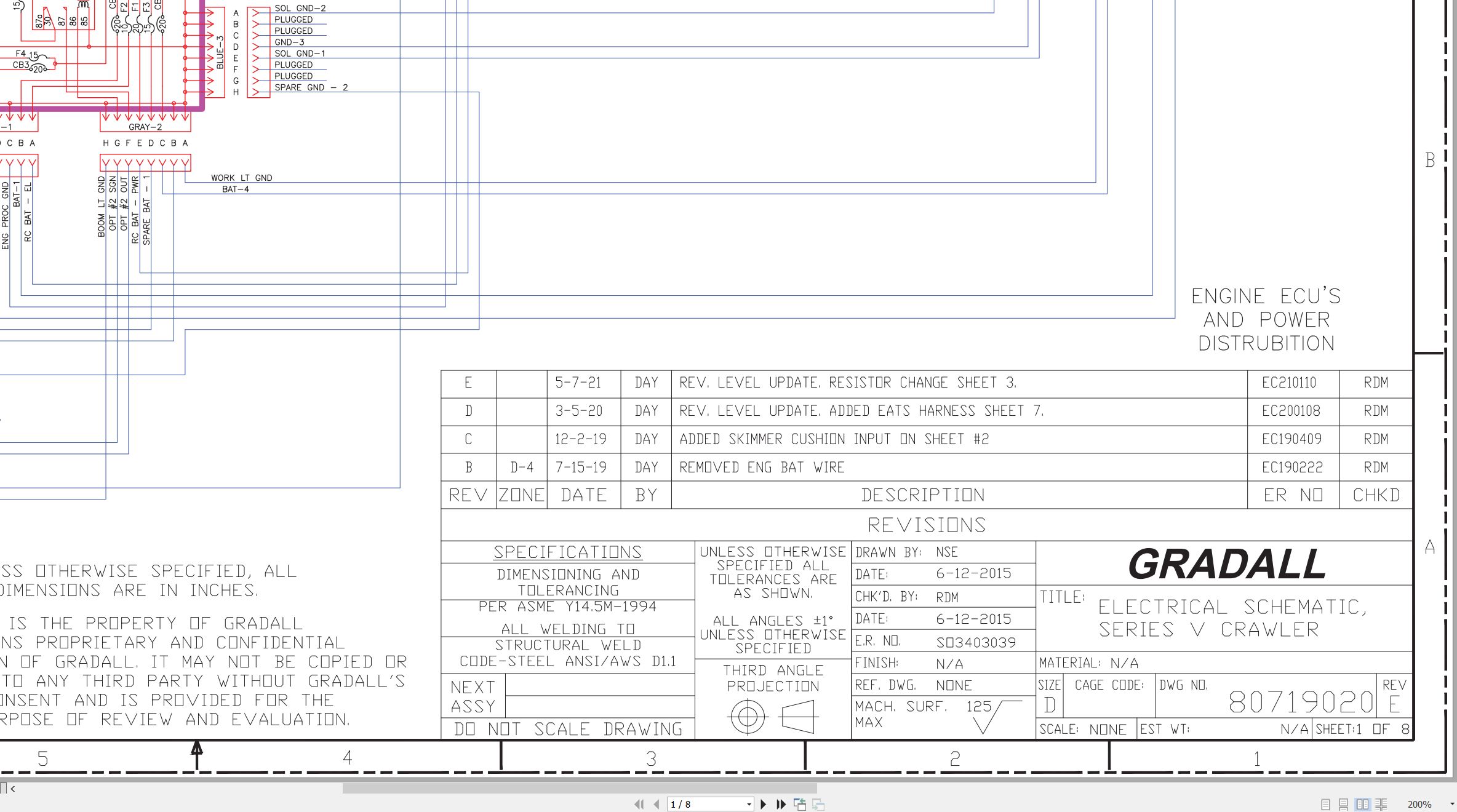
XL3200V XL3200 XL3200 to XL5210 XL5210V XL5210 XL5210V Electrical Schematic 80719020.pdf (8 Pages)
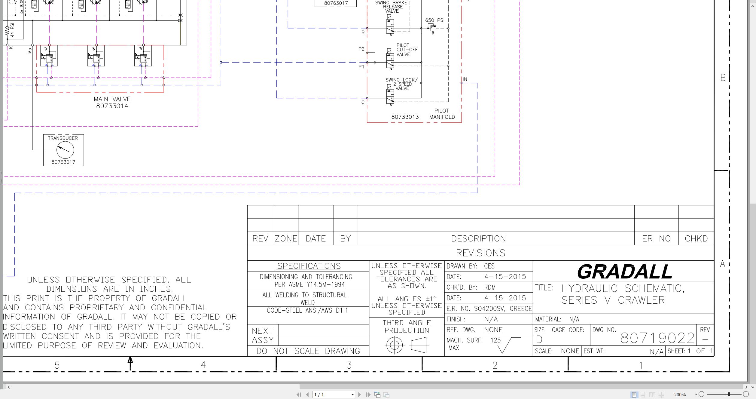
XL3200V XL3200V XL3200V to XL5210V XL5210V XL5210V Hydraulic Schematic 80719022.pdf (1 Pages)
XL3200III XL4200III XL5200III XL3210III XL4210III to XL3220III Illustrated Parts Manual 80744001 2026.pdf (656 Pages)
Contents:
Understanding Your Manual
Section 1 – Frame & Attaching Parts
Section 2 – Boom
Section 3 – Attachments
Section 4 – Engine & Attaching Parts
Section 5 – Drive Train
Section 6 – Cab
Section 7 – Controls
Section 8 – Hydraulic Circuits
Section 9 – Hydraulic Components
Section 10 – Electrical
Section 11 – Decals
Section 12 – Options
Recommended Spare Parts
Part Number Index
XL3200III XL4200III XL5200III XL3210III XL5210III to XL3220III Operator Safety Manual 80744002 2024.pdf (116 Pages)
Contents:
Section 1 – General Safety Practices
1.1 Hazard Classification System
1.2 General Precautions
1.3 Operation Safety
1.4 Personal Protection Equipment
Section 2 – Pre-Operation and Controls
2.1 Pre-Operation Checks & Inspection
2.2 Walk-Around Inspection
2.3 Safety Decals – XL3200III, XL4200III & XL5200III
2.4 Safety Decals – XL3200III, XL4200III & XL5200III (CE)
2.5 Safety Decals – XL3210III, XL4210III & XL5210III
2.6 Safety Decals – XL3210III, XL4210III & XL5210III (CE)
2.7 Cab Components
2.8 Cab Controls & Indicators
Section 3 – Operation
3.1 Engine Operation
3.2 Checks Before Operation
3.3 Crawler Chassis
3.4 Typical Dig Cycle
3.5 Lifting & Placing a Load – XL3200III, XL4200III & XL5200III
3.6 Lift Capacity – XL3200III, XL4200III & XL5200III
3.7 Engine Shutdown
3.8 Parking the Excavator
3.9 Preservation & Storage
Section 4 – Attachments
4.1 Approved Attachments
4.2 Unapproved Attachments
4.3 Attachment Operation
4.4 Adapter Attachment Installation
Section 5 – Lubrication & Maintenance
5.1 Introduction
5.2 General Maintenance Instructions
5.3 Service & Maintenance Schedules
5.4 Lubrication Schedules
Section 6 – Emergency Procedures
6.1 Loss Of Power
6.2 If You Get Stuck
Section 7 – Specifications
7.1 Product Specifications
7.2 Torque Chart
7.3 Fuses
Pre-Operation Inspection Checklist
Index
XL3200V XL4200V XL5200V to XL5210V XL3200V Low-Profile Illustrated Parts Manual 80744006 2025.pdf (640 Pages)
Contents:
Understanding Your Manual
Section 1 – Frame & Attaching Parts
Section 2 – Boom
Section 3 – Attachments
Section 4 – Engine & Attaching Parts
Section 5 – Drive Train
Section 6 – Cab
Section 7 – Controls
Section 8 – Hydraulic Circuits
Section 9 – Hydraulic Components
Section 10 – Electrical
Section 11 – Decals
Section 12 – Options
Recommended Spare Parts
Part Number Index
XL3200V XL4200V XL5200V XL3210V to XL3200V Low-Profile Operator Safety Manual 80744007 2026.pdf (134 Pages)
Contents:
Section 1 – General Safety Practices
1.1 Hazard Classification System
1.2 General Precautions
1.3 Operation Safety
1.4 Personal Protection Equipment
Section 2 – Pre-Operation and Controls
2.1 Pre-Operation Checks & Inspection
2.2 Walk-Around Inspection
2.3 Safety Decals – XL3200V, XL4200V & XL5200V
2.4 Safety Decals – XL3210V, XL4210V & XL5210V
2.5 Cab Components
2.6 Cab Controls & Indicators
2.7 Radio Control Electrical Panel (No Cab; optional)
2.8 Radio Control Strobe Lights
Section 3 – Operation
3.1 Engine Operation
3.2 Checks Before Operation
3.3 Crawler Chassis
3.4 Typical Dig Cycle
3.5 Lifting & Placing a Load – XL3200V, XL4200V & XL5200V
3.6 Lift Capacity – XL3200V, XL4200V & XL5200V
3.7 Engine Shutdown
3.8 Parking the Excavator
3.9 Preservation & Storage
3.10 Radio Control Activation (optional)
3.11 Parked Regeneration (Stage V Engines)
Section 4 – Attachments
4.1 Approved Attachments
4.2 Unapproved Attachments
4.3 Attachment Operation
4.4 Adapter Attachment Installation
Section 5 – Lubrication & Maintenance
5.1 Introduction
5.2 General Maintenance Instructions
5.3 Service & Maintenance Schedules
5.4 Lubrication Schedules
5.5 Boom Adjustments & Maintenance
Section 6 – Emergency Procedures
6.1 Loss Of Power
6.2 If You Get Stuck
Section 7 – Specifications
7.1 Product Specifications
7.2 Torque Chart
7.3 Fuses
Pre-Operation Inspection Checklist
Index
XL3200V XL4200V XL5200V XL3210V to XL3200V Low-Profile Service Supplement 80744008 2026.pdf (250 Pages)
Contents:
Section 1 – General Safety Practices
Section 2 – Pre-Operation and Controls
Section 3 – Operation
Section 4 – Attachments
Section 5 – Lubrication & Maintenance
Section 6 – Emergency Procedures
Section 7 – Specifications
Pre-Operation Inspection Checklist
Index
ELECTRICAL
41200184_D_Bodas System Training_3-5-2026.pdf
80719020 (E) Electrical Schematic
80763138 (A) Console Circuit Board
80763158 (H) Upper Harness
80763156 (B) Cab Harness
HYDRAULIC
80719022 (-) Hydraulic Schematic
CRAWLER
XL-Series Crawler Maintenance Manual
Introduction
Nomenclature
Track Adjustment
Shoe Contact with Rock Guard
Crawler Travel Speed
Crawler Tracking
Track Chain
Track Rollers
Idler Roller with Track Tension and Adjuster Components
Driver Sprocket
Miscellaneous
SIII Crawler Mount Vendor XL3200 XL3200III to XL4210 XL5200 XL5200III XL5210 Service Literature 2010.pdf (188 Pages)
1 About this Manual
1.1 Content
1.2 Validity of this Manual
1.3 Important Documents
1.4 Danger Labels and Pictograms
2 Safety
2.1 Basic Safety Information
2.2 Requirements on the Personnel
3 Product Description
3.1 Name Plate
3.2 Functional Description
3.3 Technical Data
4 Exchanging External Assembly Groups
4.1 Sealing the Drive Shaft
4.2 Sealing the Control Unit Housing
4.3 Replacing Seals
5 Functional Checks
5.1 Preparations
5.2 Checking the Load-Sensing Control (S)
5.3 Checking the Power Control (LR)
5.4 Checking the Pressure Control (D)

REALEASE :
REALEASE :

REALEASE :
REALEASE :

REALEASE :
REALEASE :

REALEASE :
REALEASE :

REALEASE :
REALEASE :

REALEASE :
REALEASE :

REALEASE :
REALEASE :

REALEASE :
REALEASE :
 Automotive - Heavy Equipment - Truck & Bus - Forklift - Crane