
3 ITEMSVIEW CART


Total: 60.00
Expert Support
Full Speed
100% Working
30 USD
List of Files:
XL7320V Illustrated Parts Manual 73204086 2025.pdf (478 Pages)
Contents:
Section 1 Frame & Attaching Parts
Section 2 Boom
Section 3 Attachments
Section 4 Engine & Attaching Parts
Section 5 Drive Train
Section 6 Cab
Section 7 Controls
Section 8 Hydraulic Circuits
Section 9 Hydraulic Components
Section 10 Electrical
Section 11 Decals
Section 12 Options
Recommended Spare Parts
Part Number Index
XL7320V Operator Safety Manual 73204087 2026.pdf (100 Pages)
Contents:
Section 1 – General Safety Practices
1.1 Hazard Classification System
1.2 General Precautions
1.3 Operation Safety
1.4 Personal Protection Equipment
Section 2 – Pre-Operation and Controls
2.1 Pre-Operation Checks & Inspection
2.2 Walk-Around Inspection
2.3 Safety Decals
2.4 Cab Components
2.5 Cab Controls & Indicators
Section 3 – Operation
3.1 Engine Operation
3.2 Checks Before Operation
3.3 Brake System
3.4 Engine Shutdown
3.5 Parking the Scaler
3.6 Preservation & Storage
3.7 Parked Regeneration (Stage V Engines)
Section 4 – Attachments
4.1 Approved Attachments
4.2 Unapproved Attachments
4.3 Attachment Operation
Section 5 – Lubrication & Maintenance
5.1 Introduction
5.2 General Maintenance Instructions
5.3 Service & Maintenance Schedules
5.4 Lubrication Schedule
Section 6 – Emergency Procedures
6.1 Loss Of Power
6.2 If You Get Stuck
6.3 Towing the machine
Section 7 – Specifications
7.1 Product Specifications
7.2 Torque Chart
7.3 Fuses
Maintenance Inspection Report
Index
XL7320V Service Manual 73204088 2026.pdf (635 Pages)
Contents:
73204088_J_XL7320V COMBINED SERVICE MANUAL_4-2026
OPERATOR INSTRUCTION
73204087_I_XL7320V Operator & Safety Manual_4-2026
HYDRAULIC COMPONENTS
Main Hydraulic Pump Repair Manual (8073-3091)
Drive Motor Application & Service Manual (8033-3195)
Drive Motor Repair Instructions (8033-3195)
Swing Motor Repair Manual (8044-3019)
Swing Drive/Tilt Transmission Assembly/Disassembly Manual (8099-3635 & 8094-3002)
ELECTRICAL
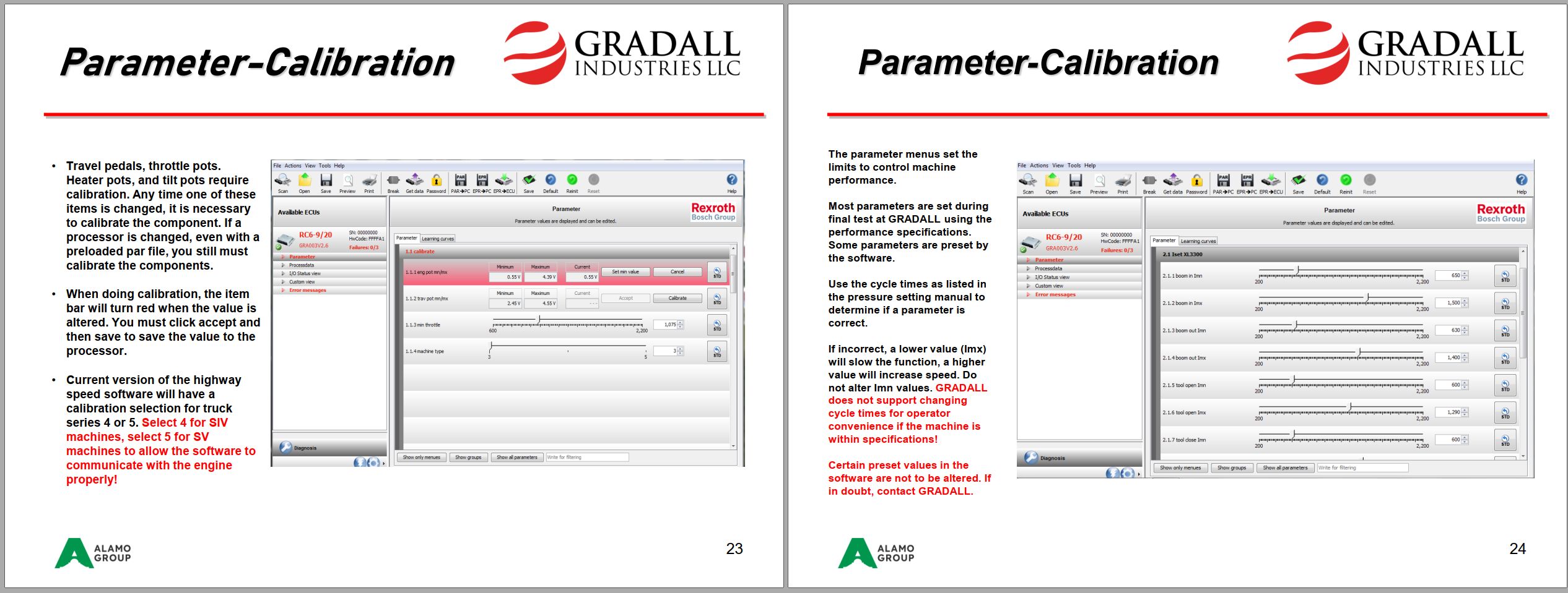
41200184_D_Bodas System Training_3-5-2026.pdf
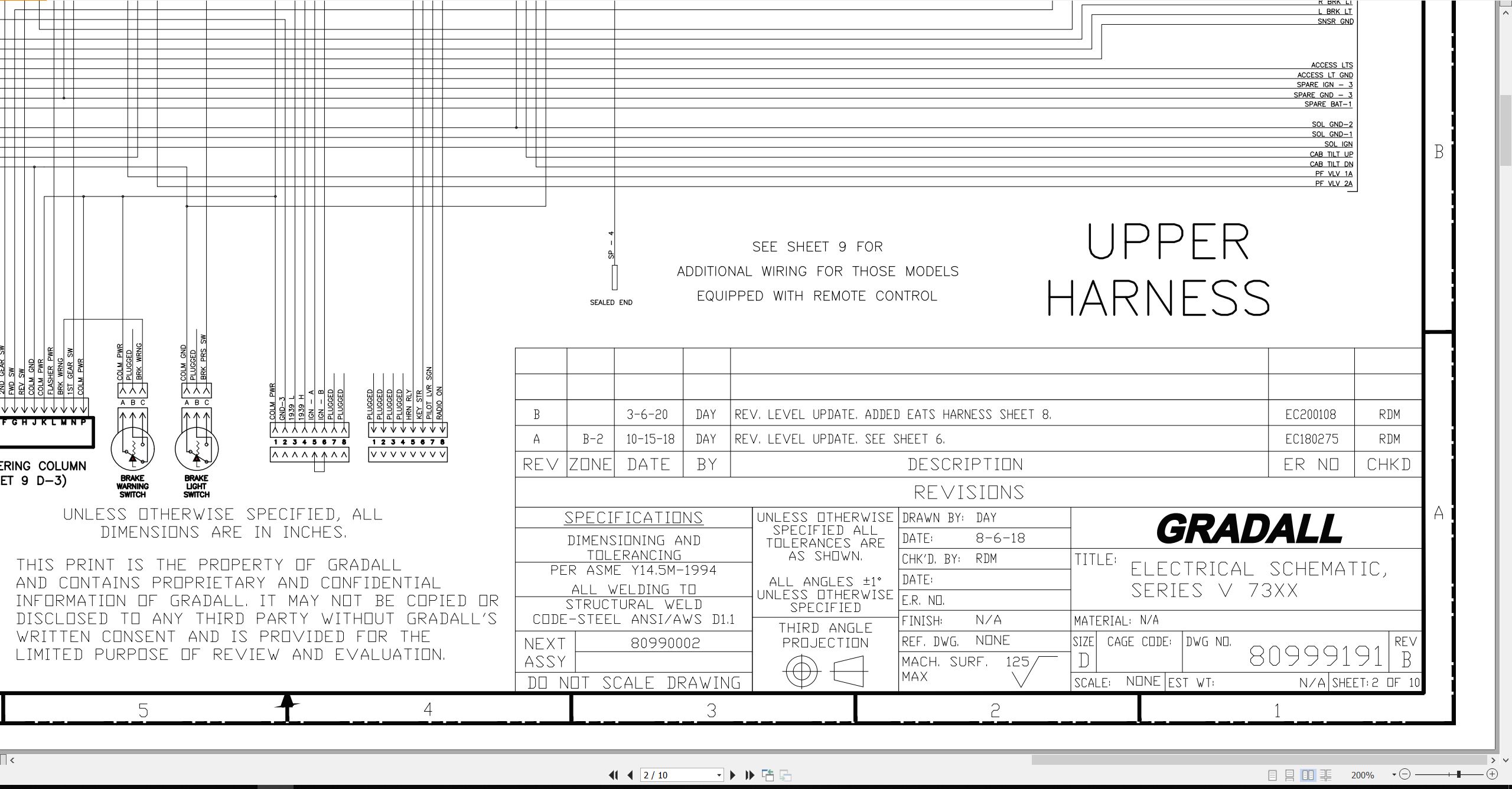
80999191_A_XL7320V Electrical Schematic_BW.pdf
PRESSURE SETTINGS & CYCLE TIMES
Final Test Report
DRIVE TRAIN
Transmission – Operation & Maintenance Manual
Transmission – Repair Manual
Front Axle Service Manual
Rear Axle Service Manual
MISCELLANEOUS
Air Filter Service Instructions (8099-3464)
XL7320II XL7320V Maintenance Inspection Report 73204098 2019.pdf (5 Pages)
Contents:
Sheet2
XL7320V Illustrated Parts Manual 73204101 2026.pdf (398 Pages)
Contents:
Section 1 Frame & Attaching Parts
Covers Installation
Upperstructure Access Installation
Upperstructure Catwalk Installation
Engine Pod Covers Installation
Engine Pod Access Installation
Tool Box/Access Panel Installation
Swing Components Installation
Section 2 Boom
Boom Installation
Boom Cradle
Main Boom Assembly
Telescope Boom Assembly (long reach)
Telescope Boom Assembly (short reach)
Boom Roller Assemblies
Boom & Cradle Hole Covers
Boom Flaps Installation
Section 3 Attachments
Scaling Hook Installation (ESCO Tooth)
Scaling Hook Installation (CAT Tooth)
Scaling Hook Installation (Hensley Tooth)
Hammer Bracket Installation
Hammer Installation (Rammer 999)
Grinder Installation
Section 4 Engine & Attaching Parts
Power Unit Installation
Power Unit Assembly
Exhaust System Installation
Air Cleaner Installation
Air Cleaner Assembly
Fuel Tank Assembly, Installation & Hosing
Fuel Tank Assembly (Quick Fill), Installation & Hosing
Cooling Unit Installation & Hosing
DEF Tank Installation
Gear Pump Installation
Engine Shutdown Installation
Section 5 Drive Train
Drivetrain Installation
Transmission – Input Housing
Transmission – Housing
Transmission – Disc Brake
Transmission – Coupling
Transmission – Planetary Drive
Transmission – Output
Transmission – Shift Sensor
Transmission – Oil Pipe
Front Axle – Hub Assembly
Front Axle – Differential & Carrier Assembly
Front Axle – Planetary Gear Drive Assembly
Front Axle – Brake Assembly
Rear Axle – Hub Assembly
Rear Axle – Differential & Carrier Assembly
Rear Axle – Planetary Gear Drive Assembly
Rear Axle – Brake Assembly
Tire/Wheel Installation
Section 6 Cab
Cab Installation Components
Operators Cab Assembly
Operators Cab
Operators Cab Door
Operators Cab Console
Pod Panel Assemblies
Operators Cab Seat Assembly
Operators Cab Seat
Seat Belt Installation
Pilot Cut-off Assembly
Evaporator & Heater Assembly (Victory Units)
Cab Air Filter Installation
Cab Mount Platform Installation & Hosing, 25° Tilt, (optional)
Cab Tilt Control Valve
Air Conditioning Installation
Section 7 Controls
Foot Pedal Assembly
Steering Column Assembly
Brake Pedal Assembly
Section 8 Hydraulic Circuits
Oil Supply to Main Hydraulic Control Valve
Oil Supply to Main Pump and Gear Pump
Hoist Cylinder Hydraulic Circuit
Boom Cylinder Hydraulic Circuit
Tool Cylinder Hydraulic Circuit (internal tool hoses)
Tool Cylinder Hydraulic Circuit (external tool hoses – long reach teleboom)
Tool Cylinder Hydraulic Circuit (external tool hoses – short reach teleboom)
Auxiliary Hydraulics Circuit (internal hoses – long reach teleboom)
Auxiliary Hydraulics Circuit (external hoses – long reach teleboom)
Auxiliary Hydraulics Circuit (external hoses – short reach teleboom)
Case Drain Circuit (short reach teleboom)
Case Drain Circuit (long reach teleboom)
Swing Hydraulic Circuit
Tilt Hydraulic Circuit
Dump Circuit
Cab Sub-Floor Plumbing
Pilot Manifold Circuit
Brake Lines and Components
Propel Hydraulic Circuit (Upper)
Propel Hydraulic Circuit (Chassis)
Oscillation Cylinder Hydraulic Circuit
Steering Cylinder Hydraulic Circuit
Section 9 Hydraulic Components
Hoist Cylinder Assembly
Boom Cylinder Assembly
Tool Cylinder Assembly
Main Hydraulic Pump
Main Hydraulic Control Valve Assembly
Main Hydraulic Control Valve
Main Hydraulic Control Valve – End Caps
Main Hydraulic Control Valve – Valve Section, Swing
Main Hydraulic Control Valve – Valve Section, Chassis Supply & Auxiliary
Hydraulic Reservoir Assembly & Installation
Swing Transmission Assembly
Swing Motor Assembly
Swing Drive Assembly
Swing Brake Assembly
Tilt Transmission
Tilt Motor Assembly
Tilt Brake Assembly
Drive Motor
Pilot Manifold Valve Module Assembly
Pilot Manifold Assembly
Center Pin Assembly
Section 10 Electrical
Electrical Installation
Electrical Installation – Engine Pod
Undercarriage Electrical Harness
Cab Console Circuit Board
Work Lights Installation
Camera Installation (split-screen)
Camera Installation (additional camera)
Section 11 Decals
Decal Installation
Section 12 Options
Auxiliary Hydraulic Filters (w/Hammer Valve) Installation
Auxiliary Hydraulic Filters (Unidirectional) Installation
Auxiliary Tube Adapter Installation
Boom Cradle Lift Saddle Installation
Boom Cradle Lift Yoke Installation (single point)
Cab Guard Installation (ROPS Certified)
Cab Guard Installation (non – ROPS Certified)
Cab Roof Guard Installation (solid peaked)
Cab Roof Guard Installation (bars)
Cab Roof Guard Installation (mesh)
Fire Extinguisher Installation
Fire Suppression System Installation (manual operation)
Front Cab Guard (bottom) Installation (solid)
Front Cab Guard (bottom) Installation (slotted)
Front Window Guard Installation (solid bars)
Front Window Guard Installation (mesh)
Front Window Guard Installation (hinged wire mesh)
Hydraulic Fluid Installation, Quintolubric 888-68
Hydraulic Fluid Installation, Ecosafe FR-68
Strobe Light (LED) Installation
Strobe Light (LED; Battery-On) Installation
Wheel Chock Brackets Installation
Recommended Spare Parts
Part Number Index
XL7320II XL7320V Final Test Report 80999099.pdf (2 Pages)
80999191BW Series V XL7320V Electrical Schematic.pdf (10 Pages)
80999191CLR XL7320 XL7320V Electrical Schematic.pdf (10 Pages)

REALEASE :
REALEASE :

REALEASE :
REALEASE :

REALEASE :
REALEASE :

REALEASE :
REALEASE :

REALEASE :
REALEASE :

REALEASE :
REALEASE :

REALEASE :
REALEASE :

REALEASE :
REALEASE :
 Automotive - Heavy Equipment - Truck & Bus - Forklift - Crane