
6 ITEMSVIEW CART


Total: 735.00
Expert Support
Full Speed
100% Working
30 USD
List of Files:
XL6210 Parts Manual 6210-4001 2017.pdf (147 Pages)
Contents:
6210-4001 PARTS MANUAL
UPPERSTRUCTURE
Section 1 INTRODUCTION
Section 2 BOOM ASSEMBLIES
Section 3 CAB & RELATED COMPONENTS
Section 4 HYDRAULIC SYSTEM COMPONENTS
Section 5 MAIN HYDRAULIC SYSTEMS
Section 6 PILOT HYDRAULIC SYSTEMS
Section 7 ATTACHMENTS
UNDERCARRIAGE
Section 1 INTRODUCTION
Section 2 UNDERCARRIAGE ASSEMBLY
Section 3 TRACK ASSEMBLY
XL6210 Service Manual 6210-4002 2006.pdf (489 Pages)
Contents:
6210-4002 XL6210 COMBINED SERVICE MANUAL
OPERATOR INSTRUCTION
29502 XL6210 Upperstructure Operation & Lubrication Manual
HYDRAULIC TESTING & ADJUSTMENTS
RDE93010-02-R Rexroth Variable Displacement Pump Service Manual
RDE92002-30 Rexroth Swing Pump Service Manual
RA64-774-S Rexroth Gear Pump Service Manual
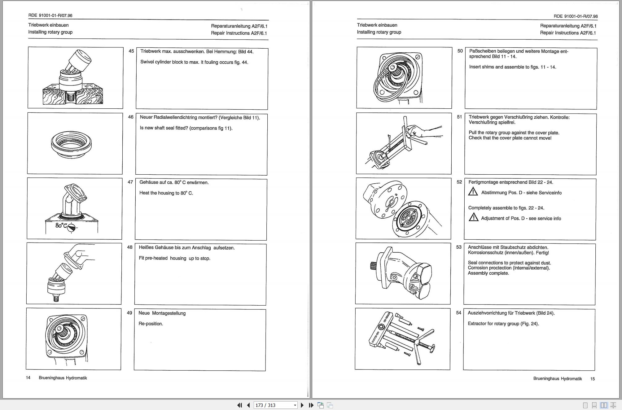
RDE91001-01-R Rexroth Swing Motor Service Manual
RA64555 Rexroth Joystick
7-124 Char-Lynn Tilt Motor Service Manual
MECHANICAL ADJUSTMENTS
29604 XL4000/5000 Upperstructure Mechanical Adjustments & Repair Manual
F74290 Ausco Swing Brake
S6A Fairfield Torque-Hub Service Manual
CRAWLER
29302 Kayaba Service Manual
29635 XL Series Crawler Maintenance Manual
MISCELLANEOUS
29710 XL5000 Series Electrical System
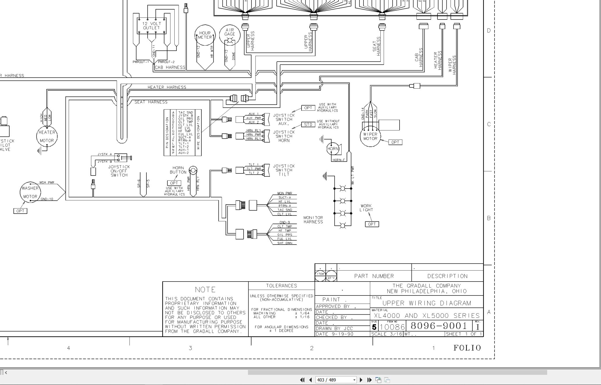
8096-9001 Upper Wiring Diagram
F114004 Donaldson Cyclopac Service Procedures
HE92-2 EMI Safety Manual – 8060-3007.pdf
Gradall Safety 2460-4161 20013
XL6210 Operators Manual 6210-4003 2095.pdf (40 Pages)
XL6210 Ilustrated Parts Manual 6210-4004 2017.pdf (278 Pages)
Contents:
Service Kits
Section 1 Frame & Attaching Parts
Figure 1-1 Frame Assembly
Figure 1-2 Rotating Platform, R.H. View
Figure 1-3 Rotating Platform, L.H. View
Figure 1-4 Swing Bearing, Cradle & Hoist Cylinder Mounting Pins & Lube System
Section 2 Boom
Figure 2-1 Boom Cradle
Figure 2-2 Main Boom Assembly
Figure 2-3 Telescope Boom Assembly
Figure 2-4 Inside Hose Trough
Figure 2-5 Roller Bracket Assembly – Concave & Flat
Figure 2-6 360 Degree Tilt Gland Assembly
Section 3 Attachments
Figure 3-1 Rammer Hammer Installation Kit
Section 4 Engine & Attaching Parts
Figure 4-1 Engine Assembly, L.H. View
Figure 4-2 Engine Assembly, R.H. View
Figure 4-3 Air Cleaner & Installation
Figure 4-4 Air Cleaner Assembly
Figure 4-5 Exhaust System
Figure 4-6 Fuel Tank Assembly
Figure 4-7 Oil Cooler, Charge Air Cooler, Radiator & Hoses
Figure 4-8 Oil Filter Assembly
Figure 4-9 Oil Filters
Figure 4-10 Auxiliary Oil Cooler
Figure 4-11 Upper Air System
Figure 4-12 Pump Coupler Assembly
Section 5 Drive Train
Figure 5-1 Track Chain & Shoes
Figure 5-2 Track Roller Assembly
Figure 5-3 Carrier Roller Assembly
Figure 5-4 Front Idler Track Adjuster Assembly
Figure 5-5 Crawler Drive Assembly
Figure 5-6 Crawler Drive Group
Section 6 Cab
Figure 6-1 Cab Assembly
Figure 6-2 Cab Door
Figure 6-3 Acoustical Liners
Figure 6-4 Cab Console
Figure 6-5 Seat Assembly
Figure 6-6 Cab Heater & Installation
Section 7 Controls
Figure 7-1 Joystick Assembly
Figure 7-2 Foot Pedals & Installation
Section 8 Hydraulic Circuits
Figure 8-1 Oil Supply to Pumps
Figure 8-2 Hydraulic Pressure to Control Valves
Figure 8-3 Hydraulic Hosing to Joysticks & Foot Operated Valves
Figure 8-4 Dump Circuit
Figure 8-5 Hoist Pilot Hydraulic Circuit
Figure 8-6 Boom Pilot Hydraulic Circuit
Figure 8-7 Tool Pilot Hydraulic Circuit
Figure 8-8 Propel Pilot Hydraulic Circuit
Figure 8-9 Swing & Swing Brake Hydraulic Circuit
Figure 8-10 Hoist Cylinder Hydraulic Circuit
Figure 8-11 Boom Cylinder Hydraulic Circuit
Figure 8-12 Tool Cylinder Hydraulic Circuit
Figure 8-13 Dual Swing Motor
Figure 8-14 Tilt Motor Hydraulic Circuit
Figure 8-15 Upper Propelling Hydraulic Circuit
Figure 8-16 Center Pin to Crawler Drives Hosing
Section 9 Hydraulic Components
Figure 9-1 Hoist Cylinder Assembly
Figure 9-2 Boom Cylinder Assembly
Figure 9-3 Tool Cylinder Assembly
Figure 9-4 Main Pump – Front
Figure 9-5 Main Pump – Rear
Figure 9-6 Hoist, Tilt, Tool Control Valve
Figure 9-7 Hoist Valve Section
Figure 9-8 Tilt Valve Section
Figure 9-9 Tool Valve Section
Figure 9-10 Boom & Propel Control Valve Assembly
Figure 9-11 Propel Valve Section
Figure 9-12 Boom Valve Section
Figure 9-13 Auxiliary Valve Section Assembly
Figure 9-14 Reservoir Assembly
Figure 9-15 Swing Pump Assembly
Figure 9-16 Swing Pump – Positioning Piston
Figure 9-17 Swing Pump – Port Block Assembly
Figure 9-18 Swing Pump – Charge Pump & DW Control
Figure 9-19 Swing Transmission Assembly
Figure 9-20 Tilt/Swing Transmission
Figure 9-21 Swing Motor
Figure 9-22 Tilt/Swing Brake
Figure 9-23 Tilt Motor
Figure 9-24 Center Pin Assembly
Figure 9-25 Gear Pump
Figure 9-26 Foot Operated Pedal Valve
Figure 9-27 Oil Filters and Hosing
Figure 9-28 Valve Assembly
Figure 9-29 Thermal By-Pass Valve
Figure 9-30 Pressure Reducing Valve Assembly
Figure 9-31 Pressure Reducing Valve
Figure 9-32 Swing Brake Release Valve
Figure 9-33 Solenoid Valve
Figure 9-34 Pilot/Steer Valve
Figure 9-35 Clamp Sets & Misc Hydraulic Components
Figure 9-36 Tilt Brake Release Valve Assembly
Section 10 Electrical
Figure 10-1 Distribution Box Assembly
Figure 10-2 Batteries, VEC & Miscellaneous Electrical Components
Figure 10-3 Gauge Panel Assembly
Section 11 Decals
Figure 11-1 Decals, Mirrors & Manuals
Section 12 Options
Figure 12-1 Air Conditioner Kit
Figure 12-2 Condensor Installation
Figure 12-3 Air Conditioner Evaporator Kit
Figure 12-4 Fire Resistant Hydraulic Fluid Installation
Figure 12-5 Window Guard Installation
Figure 12-6 Roof Guard Installation
Recommended Spare Parts
Part Number Index
XL6210 Opertor & Safety Manual 6210-4005 2008.pdf (76 Pages)
Contents:
Section 1 – General Safety Practices
1.1 Hazard Classification System
1.2 General Precautions
1.3 Operation Safety
1.4 Personal Protection Equipment
Section 2 – Pre-Operation and Controls
2.1 Pre-Operation Checks & Inspection
2.2 Walk-Around Inspection
2.3 Safety Decals
2.4 Cab Controls & Indicators
Section 3 – Operation
3.1 Engine Operation
3.2 Checks Before Operation
3.3 Crawler Chassis
3.4 Typical Dig Cycle
3.5 Engine Shutdown
3.6 Parking the Excavator
3.7 Preservation & Storage
Section 4 – Attachments
4.1 Approved Attachments
4.2 Unapproved Attachments
4.3 Attachment Operation
Section 5 – Lubrication & Maintenance
5.1 Introduction
5.2 General Maintenance Instructions
5.3 Service & Maintenance Schedule
Section 6 – Emergency & Transport Procedures
6.1 Loss Of Power
6.2 Lifting the Machine
Section 7 – Specifications
7.1 Product Specifications
7.2 Torque Chart
7.3 Fuses
Index
XL6210 Combined Service Manual 6210-4006 2008.pdf (313 Pages)
Contents:
6210-4006 XL6210 COMBINED SERVICE MANUAL
OPERATOR INSTRUCTION
6210-4005 XL6210 Operator & Safety Manual
HYDRAULIC TESTING & ADJUSTMENTS
8091-9015 Hydraulic Schematic
RDE93010-40-R Rexroth Main Pump Repair Manual
RA 92003-S Rexroth Swing Pump Application & Service Manual
RA 10 097-S Rexroth Gear Pump Service Manual
RDE91001-01-R Rexroth Swing Motor Service Manual
RE64555 Rexroth Joystick
MECHANICAL ADJUSTMENTS
74290 Ausco Swing Brake
CRAWLER
Caterpillar Crawler Operation & Maintenance Manual
MISCELLANEOUS
80909013 Start Up Procedure
F114005 Donaldson Cyclopac Service Procedure
HE92-2 EMI Safety Manual
20013 Gradall Safety Manual

REALEASE :
REALEASE :

REALEASE :
REALEASE :

REALEASE :
REALEASE :

REALEASE :
REALEASE :

REALEASE :
REALEASE :

REALEASE :
REALEASE :

REALEASE :
REALEASE :

REALEASE :
REALEASE :
 Automotive - Heavy Equipment - Truck & Bus - Forklift - Crane