
17 ITEMSVIEW CART


Total: 1,320.00
Expert Support
Full Speed
100% Working
30 USD
List of Files:
XL4210 Combined Service Manual 4210-4002 2002.pdf (490 Pages)
Contents:
4210-4002 XL4210 COMBINED SERVICE MANUAL
OPERATOR INSTRUCTION
29501 Upperstructure Operation & Lube Manual
HYDRAULIC TESTING & ADJUSTMENTS
8061-9009 Crawler Hydraulic Schematic
RDE93010-02-R Rexroth Main Pump
RDE92002-30 Rexroth Swing Pump
RA64-774-S Rexroth Gear Pump
RDE91001-01-R Rexroth Swing Motor
RA64555 Rexroth Joystick
7-124 Char-Lynn Tilt Motor
MECHANICAL ADJUSTMENTS
29604 Upperstructure Mechanical Adjustments & Repair
F36758 Ausco Swing Brake
S6A Fairfield Torque-Hub Service Manual
CRAWLER
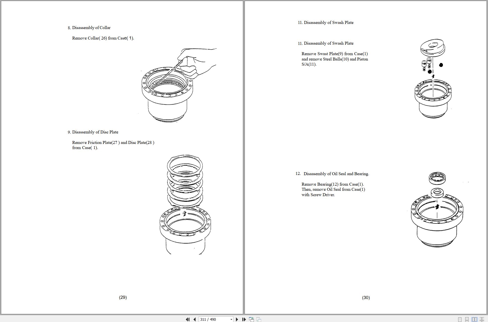
29302 Kayaba Service Manual
29635 XL Series Crawler Maintenance Manual
MISCELLANEOUS
29710 XL4000 Series Electrical Systems
8096-9001 Upper Wiring Diagram
F114004 Donaldson Cyclopac Service Procedure
HE92-2 EMI Safety Manual
20013 Gradall Safety Manual
XL4210 Upperstructure Operation & Lubrication Manual 4210-4003 .pdf (38 Pages)
XL4210 Illustrated Parts Manual 42104001 2024.pdf (450 Pages)
Contents:
Service Kits
Section 1 Frame & Attaching Parts
Figure 1-1 Frame Assembly
Figure 1-2 Rotating Platform R.H. View
Figure 1-3 Rotating Platform L.H. View
Figure 1-4 Swing Bearing, Cradle & Hoist Cylinder Mounting
Section 2 Boom
Figure 2-1 Boom Cradle
Figure 2-2 Main Boom & Roller Assemblies
Figure 2-3 Telescope Boom Assembly
Figure 2-4 Inside Hose Trough
Figure 2-5 Boom Roller Assemblies
Figure 2-6 360 Degree Tilt Gland
Figure 2-7 Bucket Linkage
Section 3 Attachments
Section 4 Engine & Attaching Parts
Figure 4-1 Engine, L.H. View
Figure 4-2 Engine, R.H. View
Figure 4-3 Air Cleaner & Installation
Figure 4-4 Air Cleaner Assembly
Figure 4-5 Exhaust System
Figure 4-6 Fuel Tank Assembly
Figure 4-7 Oil Cooler, Radiator & Hoses
Section 5 Drive Train
Figure 5-1 Track Chain & Shoes
Figure 5-2 Track Roller Assembly
Figure 5-3 Front Idler Track Adjuster Assembly
Figure 5-4 Crawler Drive Control Assembly
Figure 5-5 Crawler Drive Hydraulic Motor Assembly
Figure 5-6 Crawler Drive Gearbox
Section 6 Cab
Figure 6-1 Cab Assembly
Figure 6-2 Cab Door
Figure 6-3 Acoustical Liners
Figure 6-4 Cab Console
Figure 6-5 Seat Assembly
Figure 6-6 Cab Heater & Installation
Figure 6-7 Upper Air System
Section 7 Controls
Figure 7-1 Joystick Assembly
Figure 7-2 Foot Pedals & Installation
Section 8 Hydraulic Circuits
Figure 8-1 Oil Supply to Pumps
Figure 8-2 Hydraulic Pressure to Control Valves
Figure 8-3 Swing & Swing Brake Hydraulic Circuit
Figure 8-4 Swing Motor Hydraulic Circuit
Figure 8-5 Boom Cylinder Hydraulic Circuit
Figure 8-6 Tilt Motor Hydraulic Circuit
Figure 8-7 Hoist Cylinder Hydraulic Circuit
Figure 8-8 Tool Cylinder Hydraulic Circuit
Figure 8-9 Upper Propelling Hydraulic Circuit
Figure 8-10 Dump Circuit
Figure 8-11 Hydraulic Hosing to Joystick & Foot Operated Pedals
Figure 8-12 Boom Pilot Hydraulic Circuit
Figure 8-13 Hoist Pilot Hydraulic Circuit
Figure 8-14 Tool Pilot Hydraulic Circuit
Figure 8-15 Propel Pilot Hydraulic Circuit
Figure 8-16 Center Pin Housing
Figure 8-17 Drive Assembly Drain Hoses
Figure 8-18 Oil Filters & Hosing
Section 9 Hydraulic Components
Figure 9-1 Hoist Cylinder Assembly
Figure 9-2 Boom Cylinder
Figure 9-3 Tool Cylinder
Figure 9-4 Main Pump
Figure 9-5 Main Pump
Figure 9-6 Hoist, Tilt, Tool Control Valve
Figure 9-7 Hoist Valve Section
Figure 9-8 Tilt Valve Section
Figure 9-9 Tool Valve Section
Figure 9-10 Boom and Propel Control Valve
Figure 9-11 Propel Valve Section
Figure 9-12 Boom Valve Section
Figure 9-13 Auxiliary Valve Section Assembly
Figure 9-14 Swing Transmission
Figure 9-15 Swing Transmission Assembly
Figure 9-16 Swing Motor
Figure 9-17 Swing Brake
Figure 9-18 Tilt Transmission Assembly
Figure 9-19 Tilt Motor
Figure 9-20 Swing Pump Assembly (80933003)
Figure 9-21 Swing Pump Assembly (80933317)
Figure 9-22 Swing Pump Assembly (80933370)
Figure 9-23 Reservoir Assembly
Figure 9-24 Centerpin Assembly
Figure 9-25 Gear Pump
Figure 9-26 Foot Operated Pedal Valve
Figure 9-27 Oil Filter Assembly
Figure 9-28 Oil Filter Assemblies
Figure 9-29 Valve Assembly
Figure 9-30 Thermal By-Pass Valve
Figure 9-31 Pressure Reducing Valve Assembly
Figure 9-32 Swing Brake Release Valve
Figure 9-33 Solenoid Valve
Figure 9-34 Pilot/Steer Valve Assembly
Figure 9-35 Clamp Sets & Misc. Hydraulic. Components
Section 10 Electrical
Figure 10-1 Distribution Box Assembly
Figure 10-2 Batteries & Miscellaneous Electrical Components
Section 11 Decals
Figure 11-1 Decals
Section 12 Options
Figure 12-1 Air Conditioner Installation
Figure 12-2 Air Conditioning Evaporator Kit
Figure 12-3 Auxiliary Fan Installation Components
Figure 12-4 Aux. Hyd. Valve Field Installation Components
Figure 12-5 Additional Battery Installation Components
Figure 12-6 Cold Start Installation Components
Figure 12-7 Engine Block Heater Installation Components
Figure 12-8 Engine Shutdown Installation Components
Figure 12-9 Floodlight Installation Components
Figure 12-10 Four-Line Hose Trough Installation Components
Figure 12-11 Auxiliary Oil Cooler Installation Components
Figure 12-12 Roof Hatch Installation Components
Figure 12-13 Operating Decals
Figure 12-14 Seat Belt Installation Components
Figure 12-15 Tilt Hose Trough Installation Components
Figure 12-16 Valve Module, Auxiliary Hydraulic Installation Components
Figure 12-17 Vandal Covers Installation Components
Figure 12-18 Vandal Covers Installation Components
Figure 12-19 Wiper/Washer Installation Components
Figure 12-20 Wiper/Washer Installation Components
Figure 12-21 Battery Disconnect Switch Installation
Figure 12-22 Hammer Oiler Installation Components
Recommended Spare Parts
Part Number Index
XL4200 XL4210 Hydraulic Schematic 80619009 2001.pdf (1 Pages)
XL3210 XL3210III XL4210 XL4210III XL5210 XL5210III Electrical Schematic 80719006.pdf (6 Pages)
XL3210 XL3210III XL4210 XL4210III XL5210 XL5210III Hydraulic Schematic 80719007.pdf (1 Pages)
XL3200V XL3200 XL3200 to XL5210 XL5210V XL5210 XL5210V Electrical Schematic 80719020.pdf (8 Pages)
XL3200V XL3200V XL3200V to XL5210V XL5210V XL5210V Hydraulic Schematic 80719022.pdf (1 Pages)
XL3200III XL4200III XL5200III XL3210III XL4210III to XL3220III Illustrated Parts Manual 80744001 2026.pdf (656 Pages)
Contents:
Understanding Your Manual
Section 1 – Frame & Attaching Parts
Frame Assembly, XL3200III, XL3220III & XL3210III
Frame Assembly, XL3200III Low-Profile
Frame Assembly, XL4200III, XL4210III, XL5200III & XL5210III
Upperstructure Mirror Installation (old-style)
Upperstructure Mirror Installation (new-style)
Upperstructure Covers Installation, XL3200III, XL3200III Low-Profile, XL4200III & XL5200III
Upperstructure Covers Installation, XL3210III, XL3220III, XL4210III & XL5210III
Valve Cover, XL3200III, XL3200III Low-Profile, XL4200III & XL5200III
Valve Cover, XL3210III, XL3220III, XL4210III & XL5210III
Left Front Door, XL3200III, XL3200III Low-Profile, XL4200III & XL5200III
Left Rear Door, XL3200III, XL3200III Low-Profile, XL4200III & XL5200III
Fuel Tank & Reservoir Installation
Fuel Tank & Reservoir Assembly, XL3200III, XL3200III Low-Profile, XL4200III & XL5200III
Fuel Tank & Reservoir Assembly, XL3210III, XL4210III & XL5210III
Swing Bearing Installation Components
Counterweight & Swing Light Installation, XL3200III, XL3220III & XL3210III
Counterweight & Swing Light Installation, XL4200III, XL4210III, XL5200III & XL5210III
Counterweight Bumpers Installation, XL3200III Low-Profile, XL3210III, XL3220III, XL4210III & XL5210III
Boom Installation Components
Cab Installation Components, XL3200III, XL3200III Low-Profile, XL4200III & XL5200III
Cab Installation Components, XL3210III, XL3220III, XL4210III & XL5210III
Power Unit Installation
Section 2 – Boom
Boom Cradle, XL3200III & XL4200III
Boom Cradle, XL3200III Low-Profile
Boom Cradle, XL5200III
Boom Cradle, XL3210III, XL3220III, XL4210III & XL5210III
Main Boom Assembly, XL3200III & XL4200III
Main Boom Assembly, XL3200III Low-Profile
Main Boom Assembly, XL5200III
Main Boom Assembly, XL3210III, XL3220III, XL4210III & XL5210III
Telescope Boom Assembly, XL3200III, XL4200III & XL5200III
Telescope Boom Assembly, XL3200III Low-Profile
Telescope Boom Assembly, XL3210III, XL4210III & XL5210III
Boom Roller Assemblies
Bucket Linkage, XL3200III, XL4200III & XL5200III
Bucket Linkage, XL3200III Low-Profile
Bucket Linkage, XL3210III, XL3220III, XL4210III & XL5210III
Section 3 – Attachments
24” & 30” Excavating Buckets
30” Excavating Bucket (Pin-On)
36” Excavating Buckets
42” Excavating Bucket
48” Excavating Bucket
30” & 42” High Capacity Excavating Buckets (No Teeth)
15” Trenching Bucket
18” & 28” Pavement Removal Buckets
24” & 40” Pavement Removal Buckets
24” Ditching Bucket (No Teeth)
30” & 60” Ditching Buckets
60” Ditching Bucket w/Bolt-on Cutting Edge
66” Ditching Bucket
66” Ditching Bucket w/Bolt-on Cutting Edge
72” Ditching Bucket
72” Ditching Bucket (Pin-On)
72” & 108” Dredging Buckets
Alamo 48” Flail Mower Installation
Alamo 50” Rotary Mower Assembly
Alamo 60” Rotary Mower Assembly
4’, 6’, 8’ & 12’ Boom Extension
Auxiliary Hydraulics, 4’, 6’, 8’ & 12’ Boom Extension
Telestick Installation, XL4200III
Telestick Installation, XL5200III
Guardrail Back Scraper
2184MM & 2800MM Conveyor Buckets (Pin-On)
8’ Grading Blade & Single Tooth Ripper
Mine Bucket
Tree Limb Shear Assembly
Fixed Thumb Grapple Assembly
Hydraulic Thumb Grapple Assembly
Single & Double Tooth Scaling Hooks
Single & Double Tooth Scaling Hooks (Pin-On)
Hammer (Rammer S27) w/Hammer Adapter Installation
Hammer (Rammer S27) w/Hammer Bracket Installation (Pin-On)
Hammer (Rammer S29) w/Hammer Adapter Installation
Hammer (Rammer S29) w/Hammer Bracket Installation (Pin-On)
Hammer (Rammer S27 & S29) w/Quick Switch Adapter Installation
Hammer (Rammer S27 & S29) Bracket Assemblies
Hammer (Rammer 999) w/Quick Switch Adapter Installation
Air Hammer (Kent 999) Installation (Pin-On), XL3210III, XL4210III & XL5210III
Hammer (Atlas SB552) Installation
Section 4 – Engine & Attaching Parts
Power Unit Assembly
Muffler Support Components
Air Cleaner Installation
Air Cleaner Assembly
Cooling Unit Installation
Gear Pump Installation
Section 5 – Drive Train
Track Chain & Shoes Assembly, XL3200III, XL3200III Low-Profile, XL3220III & XL3210III
Track Chain & Shoes Assembly, XL4200III, XL4210III, XL5200III & XL5210III
Crawler Drive Motor Assembly – Control
Crawler Drive Motor Assembly – Hydraulic Motor
Crawler Drive Motor Assembly – Gearbox
Section 6 – Cab
Operators Cab Assembly, XL3200III, XL3200III Low-Profile, XL4200III & XL5200III
Operators Cab Assembly, XL3210III, XL3220III, XL4210III & XL5210III
Operators Cab, XL3200III, XL3200III Low-Profile, XL4200III & XL5200III
Operators Cab, XL3210III, XL3220III, XL4210III & XL5210III
Operators Cab Door, XL3200III, XL3200III Low-Profile, XL4200III & XL5200III
Operators Cab Door, XL3210III, XL3220III, XL4210III & XL5210III
Operators Cab Console
Pod Panel Assemblies
Operators Cab Seat Assembly
Operators Cab Seat
Pilot Cut-off Assembly
Evaporator & Heater Assembly
Air Conditioning Installation
Cab Heat Shield Installation, XL3210III, XL4210III & XL5210III
Section 7 – Controls
Foot Pedal Plate Assembly
Section 8 – Hydraulic Circuits
Hydraulic Pressure to Control Valves
Main Valve to Pilot Manifold, XL3200III, XL3200III Low-Profile, XL4200III & XL5200III
Main Valve to Pilot Manifold, XL3210III, XL4210III & XL5210III
Dump Circuit
Hoist Cylinder Hydraulic Circuit, XL3200III, XL3210III, XL3220III, XL4200III, XL4210III, XL5200III, XL5210III
Hoist Cylinder Hydraulic Circuit, XL3200III Low-Profile
Hoist Tubes Replacement Kit
Boom Cylinder Hydraulic Circuit, XL3200III, XL4200III & XL5200III
Boom Cylinder Hydraulic Circuit, XL3200III Low-Profile
Boom Cylinder Hydraulic Circuit, XL3210III, XL3220III, XL4210III & XL5210III
Tool Cylinder Hydraulic Circuit, XL3200III, XL4200III & XL5200III
Tool Cylinder Hydraulic Circuit, XL3200III Low-Profile
Tool Cylinder Hydraulic Circuit, XL3210III, XL3220III, XL4210III & XL5210III
Auxiliary Hydraulic Circuit, XL3200III Low-Profile
Tilt Motor Hydraulic Circuit, XL3200III, XL3200III Low-Profile, XL4200III & XL5200III
Tilt Motor Hydraulic Circuit, XL3210III, XL3220III, XL4210III & XL5210III
Swing Motor Hydraulic Circuit
Swing Tubes Replacement Kit
Upper Propelling Hydraulic Circuit
Crawler Drive Main Hydraulic Circuit
Crawler Drive Forward/Reverse Hydraulic Circuit
Section 9 – Hydraulic Components
Hoist Cylinder Assembly, XL3200III, XL3220III & XL3210III
Hoist Cylinder Assembly, XL3200III Low-Profile
Hoist Cylinder Assembly, XL4200III & XL4210III
Hoist Cylinder Assembly, XL5200III & XL5210III
Boom Cylinder Assembly, XL3200III & XL3210III
Boom Cylinder Assembly, XL3200III Low-Profile
Boom Cylinder Assembly, XL4200III & XL4210III
Boom Cylinder Assembly, XL5200III & XL5210III
Tool Cylinder Assembly, XL3200III
Tool Cylinder Assembly, XL3200III Low-Profile
Tool Cylinder Assembly, XL4200III & XL5200III
Tool Cylinder Assembly, XL3210III, XL4210III & XL5210III
Main Hydraulic Pump
Main Hydraulic Control Valve Assembly
Main Hydraulic Control Valve
Main Hydraulic Control Valve – End Caps
Main Hydraulic Control Valve – Valve Section, Swing
Main Hydraulic Control Valve – Valve Section, Tilt & Auxiliary
Pilot Manifold Valve Tray Hydraulic Components, XL3200III, XL3200III Low-Profile, XL4200III & XL5200III
Pilot Manifold Valve Tray Hydraulic Components, XL3210III, XL3220III, XL4210III & XL5210III
Pilot Manifold Assembly
Swing Transmission Assembly
Swing Motor Assembly
Swing Drive Assembly
Swing Brake Assembly
Tilt Transmission Assembly, XL3200III, XL3200III Low-Profile, XL4200III & XL5200III
Tilt Transmission Assembly, XL3210III, XL3220III, XL4210III & XL5210III
Tilt Drive Assembly, XL3200III, XL3200III Low-Profile, XL4200III & XL5200III
Tilt Transmission, XL3210III, XL3220III, XL4210III & XL5210III
Tilt Motor Assembly, XL3200III, XL3200III Low-Profile, XL4200III & XL5200III
Tilt Motor Assembly, XL3210III, XL3220III, XL4210III & XL5210III
Tilt Brake Assembly, XL3200III, XL3200III Low-Profile, XL4200III & XL5200III
Tilt Brake Assembly, XL3210III, XL3220III, XL4210III & XL5210III
Center Pin Assembly
Section 10 – Electrical
Electrical Components
Battery Installation
Service Panel Assembly
Cab Console Circuit Board
Work Lights Installation
Section 11 – Decals
Decals Installation, XL3200III, XL3200III Low-Profile, XL4200III & XL5200III
Decals Installation, XL3210III, XL3220III, XL4210III & XL5210III
Section 12 – Options
Air Hammer (Kent 999) Supply Plumbing Installation, XL3210III, XL4210III & XL5210III
Air Hammer (Kent 999) Air Line Oiler Installation, XL3210III, XL4210III & XL5210III
Attachment Case Drain Installation, XL3200III & XL3210III
Auxiliary Cab Fan Installation
Auxiliary Hydraulic Plumbing Installation, XL3200III, XL4200III & XL5200III
Auxiliary Hydraulic Plumbing Installation, XL3210III, XL3220III, XL4210III & XL5210III
Auxiliary Oil to Air Conversion Installation, XL3210II, XL4210III & XL5210III
Auxiliary Tube Adapter Installation
Battery Disconnect Switch, (Lockable)
Belly Pan Installation, XL3210III, XL4210III & XL5210III
Bolt-On Lifting Yoke Installation, XL3210III, XL4210III & XL5210III
Bolt-On Folding Lifting Yoke Installation, XL3210III, XL4210III & XL5210III
Bolt-On Crawler Step Installation, XL4200III, XL4210III, XL5200III & XL5210III
Boom Hole Covers Installation, XL5210III
Boom Top Guard Installation, XL3210III, XL3220III, XL4210III & XL5210III
Cab Air Filter Installation, XL3210III, XL4210III & XL5210III
Cab Guard Frame Installation, XL3210III, XL4210III & XL5210III
Cab Guard Frame Installation, XL3210III, XL4210III & XL5210III
Cab Guard Installation, XL3210III, XL4210III & XL5210III
Cab Guard Installation, XL3210III, XL4210III & XL5210III
Cab Guard Installation, XL3210III, XL4210III & XL5210III
Cab Guard Installation, XL3210III, XL4210III & XL5210III
Cab Heat Shield Installation, XL3210III, XL4210III & XL5210III
Cab Roof Guard Installations, XL3200III, XL4200III & XL5200III
Cab Roof Guard Installation, XL3210III, XL4210III & XL5210III
Camera Kit Installation
Crawler Skid Plate Installation
Escape Hammer Installation
Exhaust Purifier Installation, XL3200III Low-Profile
Fire Extinguisher Installation, XL3200III, XL3200III Low-Profile, XL4200III & XL5200III
Fire Extinguisher Installation, XL3210III, XL4210III & XL5210III
Fire Supression System Installation
Foot Switch Installations, Auxiliary & Tilt Functions
Front Window Guard Installation, XL3200III, XL4200III & XL5200III
Front Window Guard Installation, XL3210III, XL4210III & XL5210III
Grid Heater Installation
Hand Rail Installation, XL3210III, XL4210III & XL5210III
Hoist Lock Installation, XL3200III & XL3210III
Hoist Lock Installation, XL4200III, XL4210III, XL5200III & XL5210III
Hoist Stop Installation
Hydraulic Fluid Installation, Quintolubric 888-68
Hydraulic Fluid Installation, Ecosafe FR-68
Hydraulic Fluid Installation, Ecosafe FR-46
Hydraulic Supressor Installation
Lifting Provisions, XL3200III Low-Profile
Lock Pin Installation
Low Pressure Aux Return Installation
Roller Bracket Guards Installation, XL3210III, XL4210III & XL5210III
Seat Belt Installations
Seat Belt Installation, 3-Point
Strobe Light Installation, XL3200III, XL4200III & XL5200III
Strobe Light w/Branch Guard Installation, XL3200III, XL4200III & XL5200III
Strobe Light (Super-LED) Installation, XL3200III, XL4200III & XL5200III
Strobe Light (roof guard mount) Installation, XL3210III, XL4210III & XL5210III
Sun Visor Installation
Swing Motor Port Jumper Circuit Installation
Tool Open Lock Installation
Vandal Covers Installation, XL3200III, XL4200III & XL5200III
Windshield Wiper Installation, XL3210III, XL4210III & XL5210III
Work Light (HID) Installation
Work Light Installation, XL3210III, XL4210III & XL5210III
Work Light (LED) Installation
Recommended Spare Parts
Part Number Index
XL3200III XL4200III XL5200III XL3210III XL5210III to XL3220III Operator Safety Manual 80744002 2024.pdf (116 Pages)
Contents:
Section 1 – General Safety Practices
1.1 Hazard Classification System
1.2 General Precautions
1.3 Operation Safety
1.4 Personal Protection Equipment
Section 2 – Pre-Operation and Controls
2.1 Pre-Operation Checks & Inspection
2.2 Walk-Around Inspection
2.3 Safety Decals – XL3200III, XL4200III & XL5200III
2.4 Safety Decals – XL3200III, XL4200III & XL5200III (CE)
2.5 Safety Decals – XL3210III, XL4210III & XL5210III
2.6 Safety Decals – XL3210III, XL4210III & XL5210III (CE)
2.7 Cab Components
2.8 Cab Controls & Indicators
Section 3 – Operation
3.1 Engine Operation
3.2 Checks Before Operation
3.3 Crawler Chassis
3.4 Typical Dig Cycle
3.5 Lifting & Placing a Load – XL3200III, XL4200III & XL5200III
3.6 Lift Capacity – XL3200III, XL4200III & XL5200III
3.7 Engine Shutdown
3.8 Parking the Excavator
3.9 Preservation & Storage
Section 4 – Attachments
4.1 Approved Attachments
4.2 Unapproved Attachments
4.3 Attachment Operation
4.4 Adapter Attachment Installation
Section 5 – Lubrication & Maintenance
5.1 Introduction
5.2 General Maintenance Instructions
5.3 Service & Maintenance Schedules
5.4 Lubrication Schedules
Section 6 – Emergency Procedures
6.1 Loss Of Power
6.2 If You Get Stuck
Section 7 – Specifications
7.1 Product Specifications
7.2 Torque Chart
7.3 Fuses
Pre-Operation Inspection Checklist
Index
XL3200V XL4200V XL5200V to XL5210V XL3200V Low-Profile Illustrated Parts Manual 80744006 2025.pdf (640 Pages)
Contents:
Understanding Your Manual
Section 1 – Frame & Attaching Parts
Frame Assembly, XL3200V & XL3210V
Frame Assembly, XL3200V Low-Profile
Frame Assembly, XL4200V, XL4210V, XL5200V & XL5210V
Upperstructure Mirror Installation
Upperstructure Mirror Installation (Steel Mirrors)
Upperstructure Covers Installation (Tier 4F Engine)
Upperstructure Covers Installation (Tier 3 Engine)
Upperstructure Covers Installation (Tier V Engine)
Valve Cover
Fuel Tank & Reservoir Installation
Fuel Tank & Reservoir Assembly (Plastic Fuel Tank)
Fuel Tank & Reservoir Assembly (Steel Fuel Tank)
Reservoir Breather Installation
Swing Bearing Installation Components
Counterweight & Swing Light Installation, XL3200V, XL3200V Low-Profile & XL3210V
Counterweight & Swing Light Installation, XL4200V, XL4210V, XL5200V & XL5210V
Counterweight Bumpers Installation, XL3200V Low-Profile, XL3210V, XL4210V & XL5210V
Boom Installation Components
Boom Installation Components, XL3200V Low-Profile
Cab Installation Components, XL3200V, XL3200V Low-Profile, XL4200V & XL5200V
Cab Installation Components, XL3210V, XL4210V & XL5210V
Section 2 – Boom
Boom Cradle, XL3200V & XL4200V
Boom Cradle, XL3200V Low-Profile
Boom Cradle, XL5200V
Boom Cradle, XL3210V, XL4210V & XL5210V
Main Boom Assembly, XL3200V & XL4200V
Main Boom Assembly, XL3200V Low-Profile
Main Boom Assembly, XL5200V
Main Boom Assembly, XL3210V, XL4210V & XL5210V
Telescope Boom Assembly, XL3200V, XL4200V & XL5200V
Telescope Boom Assembly, XL3200V Low-Profile
Telescope Boom Assembly, XL3210V, XL4210V & XL5210V
Boom Roller Assemblies
Bucket Linkage, XL3200V, XL4200V & XL5200V
Bucket Linkage, XL3200V Low-Profile
Bucket Linkage, XL3210V, XL4210V & XL5210V
Section 3 – Attachments
24” & 30” Excavating Buckets
24” & 30” Excavating Buckets (Low-Profile models only)
30” Excavating Bucket (Pin-On)
36” Excavating Buckets
42” Excavating Bucket
48” Excavating Bucket
30” & 42” High Capacity Excavating Buckets (No Teeth)
15” Trenching Bucket
18”, 28” & 30” Pavement Removal Buckets
24” & 40” Pavement Removal Buckets
24” Ditching Bucket (No Teeth)
30” & 60” Ditching Buckets
60” Ditching Bucket w/Bolt-on Cutting Edge
66” Ditching Bucket
66” Ditching Bucket w/Bolt-on Cutting Edge
72” Ditching Bucket
72” Ditching Bucket (Pin-On)
72” & 108” Dredging Buckets
4’, 6’, 8’ & 12’ Boom Extension
Auxiliary Hydraulics, 4’, 6’, 8’ & 12’ Boom Extension
Telestick Installation, XL4200V
Telestick Installation, XL5200V
Guardrail Back Scraper
2184MM & 2800MM Conveyor Buckets (Pin-On)
8’ Grading Blade & Single Tooth Ripper
Mine Bucket
Tree Limb Shear Assembly
Fixed Thumb Grapple Assembly
Hydraulic Thumb Grapple Assembly
Single & Double Tooth Scaling Hooks
Single & Double Tooth Scaling Hooks (Pin-On)
Air Hammer (Kent 999) Installation (Pin-On), XL3210V, XL4210V & XL5210V
Hammer (Atlas SB552) Installation
Hammer (Rammer 999) Installation, (Bucket Adapter Mount)
Hammer (Rammer 999) Installation, (Pin-On)
Hammer (Rammer 999) w/Quick Switch Adapter Installation
Hammer (Rammer BR1322) w/Hammer Bracket Installation
Hammer Bracket Assembly
Section 4 – Engine & Attaching Parts
Power Unit Assembly (Tier 4F Engine)
Power Unit Assembly (Tier 3 Engine)
Power Unit Assembly (Stage V Engine)
Exhaust System Installation (Tier 4F Engine)
Exhaust System Installation (Tier 3 Engine)
Exhaust System Installation (Stage V Engine)
Air Cleaner Installation (Tier 4F Engine)
Air Cleaner Installation (Tier 3 Engine)
Air Cleaner Installation (Stage V Engine)
Air Cleaner Assembly
Cooling Unit Installation (Tier 4F Engine)
Cooling Unit Installation (Tier 3 Engine)
Cooling Unit Installation (Stage V Engine)
DEF Tank Installation (Tier 4F Engine)
DEF Tank Installation (Stage V Engine)
Gear Pump Installation
Section 5 – Drive Train
Track Chain & Shoes Assembly, XL3200V, XL3200V Low-Profile & XL3210V
Track Chain & Shoes Assembly, XL4200V, XL4210V, XL5200V & XL5210V
Track Roller
Carrier Roller
Front Idler Track Adjuster
Crawler Drive Motor Assembly – Control
Crawler Drive Motor Assembly – Hydraulic Motor
Crawler Drive Motor Assembly – Gearbox
Section 6 – Cab
Operators Cab Assembly, XL3200V, XL3200V Low-Profile, XL4200V & XL5200V
Operators Cab Assembly, XL3210V, XL4210V & XL5210V
Operators Cab, XL3200V, XL3200V Low-Profile, XL4200V & XL5200V
Operators Cab, XL3210V, XL4210V & XL5210V
Operators Cab Door, XL3200V, XL3200V Low-Profile, XL4200V & XL5200V
Operators Cab Door, XL3210V, XL4210V & XL5210V
Operators Cab Console
Pod Panel Assemblies
Operators Cab Seat Assembly
Operators Cab Seat
Pilot Cut-off Assembly
Evaporator & Heater Assembly (Pro-Air Units)
Evaporator & Heater Assembly (Victory Units)
Air Conditioning Installation
Section 7 – Controls
Foot Pedal Plate Assembly
Foot Switch (Boom Tilt) Installation (optional)
Foot Switch (Aux Hydraulics – Bidirectional Flow) Installation (optional)
Foot Switch (Aux Hydraulics – Unidirectional Flow) Installation (optional)
Radio Remote Control Installation, With Cab (optional)
Radio Remote Control Installation, Without Cab (optional)
Radio Remote Controller Installation (optional)
Remote Control Transmitter/Receiver Components (optional)
Section 8 – Hydraulic Circuits
Oil Supply to Main Pump & Control Valve
Main Valve to Pilot Manifold, XL3200V, XL3200V Low-Profile, XL4200V & XL5200V
Main Valve to Pilot Manifold, XL3210V, XL4210V & XL5210V
Dump Circuit
Hoist Cylinder Hydraulic Circuit, XL3200V, XL3210V, XL4200V, XL4210V, XL5200V, XL5210V
Hoist Cylinder Hydraulic Circuit, XL3200V Low-Profile
Boom Cylinder Hydraulic Circuit, XL3200V, XL4200V & XL5200V
Boom Cylinder Hydraulic Circuit, XL3200V Low-Profile
Boom Cylinder Hydraulic Circuit, XL3210V, XL4210V & XL5210V
Tool Cylinder Hydraulic Circuit, XL3200V, XL4200V & XL5200V
Tool Cylinder Hydraulic Circuit, XL3200V Low-Profile
Tool Cylinder Hydraulic Circuit, XL3210V, XL4210V & XL5210V
Auxiliary Hydraulic Circuit, XL3200V Low-Profile
Case Drain Circuit, XL3200V, XL4200V & XL5200V (optional)
Tilt Motor Hydraulic Circuit, XL3200V, XL3200V Low-Profile, XL4200V & XL5200V
Tilt Motor Hydraulic Circuit, XL3210V, XL4210V & XL5210V
Swing Motor Hydraulic Circuit
Upper Propelling Hydraulic Circuit
Crawler Drive Main Hydraulic Circuit
Crawler Drive Forward/Reverse Hydraulic Circuit
Section 9 – Hydraulic Components
Hoist Cylinder Assembly, XL3200V & XL3210V
Hoist Cylinder Assembly, XL3200V Low-Profile
Hoist Cylinder Assembly, XL4200V & XL4210V
Hoist Cylinder Assembly, XL5200V & XL5210V
Boom Cylinder Assembly, XL3200V & XL3210V
Boom Cylinder Assembly, XL3200V Low-Profile
Boom Cylinder Assembly, XL4200V & XL4210V
Boom Cylinder Assembly, XL5200V & XL5210V
Tool Cylinder Assembly, XL3200V
Tool Cylinder Assembly, XL3200V Low-Profile
Tool Cylinder Assembly, XL4200V & XL5200V
Tool Cylinder Assembly, XL3210V, XL4210V & XL5210V
Main Hydraulic Pump
Main Hydraulic Control Valve Assembly
Main Hydraulic Control Valve
Main Hydraulic Control Valve – End Caps
Main Hydraulic Control Valve – Valve Section, Swing
Main Hydraulic Control Valve – Valve Section, Tilt & Auxiliary
Pilot Manifold Valve Tray Hydraulic Components, XL3200V, XL3200V Low-Profile, XL4200V & XL5200V
Pilot Manifold Valve Tray Hydraulic Components, XL3210V, XL4210V & XL5210V
Pilot Manifold Assembly
Swing Transmission Assembly, XL3200V, XL3200V Low-Profile, XL4200V & XL5200V
Swing Transmission Assembly, XL3210V, XL4210V & XL5210V
Swing Motor Assembly
Swing Drive Assembly, XL3200V, XL3200V Low-Profile, XL4200V & XL5200V
Swing Drive Assembly, XL3210V, XL4210V & XL5210V
Swing Brake Assembly
Tilt Transmission Assembly, XL3200V, XL3200V Low-Profile, XL4200V & XL5200V
Tilt Transmission Assembly, XL3210V, XL4210V & XL5210V
Tilt Drive Assembly, XL3200V, XL3200V Low-Profile, XL4200V & XL5200V
Tilt Transmission, XL3210V, XL4210V & XL5210V
Tilt Motor Assembly, XL3200V, XL3200V Low-Profile, XL4200V & XL5200V
Tilt Motor Assembly, XL3210V, XL4210V & XL5210V
Tilt Brake Assembly, XL3200V, XL3200V Low-Profile, XL4200V & XL5200V
Tilt Brake Assembly, XL3210V, XL4210V & XL5210V
Center Pin Assembly
Section 10 – Electrical
Electrical Components
Battery Installation
Service Panel Assembly
Cab Console Circuit Board
Section 11 – Decals
Decals Installation, XL3200V, XL3200V Low-Profile, XL4200V & XL5200V
Decals Installation, XL3210V, XL4210V & XL5210V
Section 12 – Options
Air Hammer (Kent 999) Supply Plumbing Installation, XL3210V, XL4210V & XL5210V
Air Hammer (Kent 999) Air Line Oiler Installation, XL3210V, XL4210V & XL5210V
Attachment Case Drain Installation, XL3210V
Auxiliary Hydraulic Plumbing Installation, XL3200V, XL4200V & XL5200V
Auxiliary Hydraulic Plumbing Installation, XL3210V, XL4210V & XL5210V
Auxiliary Oil to Air Conversion Installation, XL3210V, XL4210V & XL5210V
Auxiliary Tube Adapter Installation
Belly Pan Installation, XL3210V, XL4210V & XL5210V
Bolt-On Lifting Yoke Installation, XL3210V, XL4210V & XL5210V
Bolt-On Folding Lifting Yoke Installation, XL3210V, XL4210V & XL5210V
Bolt-On Crawler Step Installation, XL4200V, XL4210V, XL5200V & XL5210V
Boom Hole Covers (main boom) Installation, XL3210V, XL4210V & XL5210V
Boom Hole Covers (telescope boom) Installation, XL5210V
Boom Top Guard Installation, XL3210V, XL4210V & XL5210V
Cab Air Filter Installation, XL3200V, XL4200V & XL5200V
Cab Air Filter Installation, XL3210V, XL4210V & XL5210V
Cab Guard Installation (ROPS Certified)
Cab Guard Installation (non – ROPS Certified)
Cab Roof Guard (mount to cab lugs) Installations, XL3200V, XL4200V & XL5200V
Cab Roof Guard Installation (solid peaked)
Cab Roof Guard Installation (bars)
Cab Roof Guard Installation (mesh)
Camera Kit Installation
Camera (Split-Screen) Kit Installation
Crawler Skid Plate Installation
Engine Block Heater Installation (110v)
Escape Hammer Installation
Fire Extinguisher Installation, XL3200V, XL4200V & XL5200V
Fire Extinguisher Installation (front of cab), XL3200V, XL4200V & XL5200V
Fire Extinguisher Installation, XL3210V, XL4210V & XL5210V
Fire Supression System Installation
Front Cab Guard (bottom) Installation (solid)
Front Cab Guard (bottom) Installation (slotted)
Front Window Guard Installation (solid bars)
Front Window Guard Installation (mesh)
Front Window Guard Installation (hinged wire mesh)
Front Window (Heat Resistant) Installation
Hand Rail Installation
Hoist Lock Installation
Hoist Stop Installation
Hydraulic Fluid Installation, Quintolubric 888-68
Hydraulic Fluid Installation, Ecosafe FR-68
Hydraulic Fluid Installation, Ecosafe FR-46
Hydraulic Supressor Installation
Lock Pin Installation
Low Pressure Aux Return Installation
Roller Bracket Guards Installation, XL3210V, XL4210V & XL5210V
Seat Belt Installations
Seat Belt Installation, 3-Point
Strobe Light (LED) Installation
Strobe Light (LED) Installation, XL3200V, XL4200V & XL5200V
Strobe Light (counterweight-mounted) Installation
Strobe Light Branch Guard Installation, XL3200V, XL4200V & XL5200V
Sun Visor Installation
Swing Motor Port Jumper Circuit Installation
Tool Open Lock Installation
Two-Point Lift Ring Installation
Vandal Covers Installation, XL3200V, XL4200V & XL5200V
Window Guard Installation, XL3200V, XL4200V & XL5200V
Work Light Installation
Work Light (LED) Installation
Work Light Guards Installation
Work Light (Hi-Temp) Installation, XL3210V, XL4210V & XL5210V
Work Light (Hi-Temp) Installation, XL3210V, XL4210V & XL5210V Remote Control – (No Cab)
Zone Lights (Red Stripe LED) Installation
Recommended Spare Parts
Part Number Index
XL3200V XL4200V XL5200V XL3210V to XL3200V Low-Profile Operator Safety Manual 80744007 2026.pdf (134 Pages)
Contents:
Section 1 – General Safety Practices
1.1 Hazard Classification System
1.2 General Precautions
1.3 Operation Safety
1.4 Personal Protection Equipment
Section 2 – Pre-Operation and Controls
2.1 Pre-Operation Checks & Inspection
2.2 Walk-Around Inspection
2.3 Safety Decals – XL3200V, XL4200V & XL5200V
2.4 Safety Decals – XL3210V, XL4210V & XL5210V
2.5 Cab Components
2.6 Cab Controls & Indicators
2.7 Radio Control Electrical Panel (No Cab; optional)
2.8 Radio Control Strobe Lights
Section 3 – Operation
3.1 Engine Operation
3.2 Checks Before Operation
3.3 Crawler Chassis
3.4 Typical Dig Cycle
3.5 Lifting & Placing a Load – XL3200V, XL4200V & XL5200V
3.6 Lift Capacity – XL3200V, XL4200V & XL5200V
3.7 Engine Shutdown
3.8 Parking the Excavator
3.9 Preservation & Storage
3.10 Radio Control Activation (optional)
3.11 Parked Regeneration (Stage V Engines)
Section 4 – Attachments
4.1 Approved Attachments
4.2 Unapproved Attachments
4.3 Attachment Operation
4.4 Adapter Attachment Installation
Section 5 – Lubrication & Maintenance
5.1 Introduction
5.2 General Maintenance Instructions
5.3 Service & Maintenance Schedules
5.4 Lubrication Schedules
5.5 Boom Adjustments & Maintenance
Section 6 – Emergency Procedures
6.1 Loss Of Power
6.2 If You Get Stuck
Section 7 – Specifications
7.1 Product Specifications
7.2 Torque Chart
7.3 Fuses
Pre-Operation Inspection Checklist
Index
XL3200V XL4200V XL5200V XL3210V to XL3200V Low-Profile Service Supplement 80744008 2026.pdf (250 Pages)
Contents:
Section 1 – General Safety Practices
Section 2 – Pre-Operation and Controls
Section 3 – Operation
Section 4 – Attachments
Section 5 – Lubrication & Maintenance
Section 6 – Emergency Procedures
Section 7 – Specifications
Pre-Operation Inspection Checklist
Index
ELECTRICAL
41200184_D_Bodas System Training_3-5-2026.pdf
Slide 1: BODAS Use & Operation Guide
Slide 2: BODAS – Program Notes
Slide 3: Program Notes (Continued)
Slide 4: Processor & Software
Slide 5: BODAS Software
Slide 6: Serial Communications Cable
Slide 7: This Doesn’t Work!
Slide 8: CAN Communication Port
Slide 9: Program Setup
Slide 10: Program Setup (Continued)
Slide 11: Program Setup (Continued)
Slide 12: Program Setup (Continued)
Slide 13
Slide 14: Using Bodas
Slide 15: Using Bodas (Continued)
Slide 16: Using Bodas (Continued)
Slide 17: Using Bodas (Continued)
Slide 18: Using Bodas (Continued)
Slide 19
Slide 20: Bodas Menus
Slide 21
Slide 22: Parameter-Calibration
Slide 23: Parameter-Calibration
Slide 24: Parameter-Calibration
Slide 25: Parameter-Calibration Expanded
Slide 26: Parameter-Calibrations
Slide 27: Parameter-Calibrations
Slide 28: Parameter- Machine and Truck type
Slide 29: Parameter- Unlocking
Slide 30: Parameter- Unlocked Parameters
Slide 31: Parameter- Unlocked Parameters
Slide 32: Parameter Settings
Slide 33: Parameter Menus Expanded
Slide 34: Parameter Menus Expanded
Slide 35: Parameter Menus Expanded
Slide 36: Parameter Menus Expanded
Slide 37: Parameter Menu Details
Slide 38: Parameter Menus Detail & Adjustments
Slide 39: Parameter Menus Detail & Adjustments
Slide 40
Slide 41: Error Messages
Slide 42: Error Messages (Continued)
Slide 43: Error Messages (Continued)
Slide 44
Slide 45: Processdata Menu
Slide 46: Processdata Menu (Continued)
Slide 47: Processdata Menu (Continued)
Slide 48: Processdata Menu (Continued)
Slide 49: Processdata Menu (Continued)
Slide 50: Processdata Menu (Continued)
Slide 51: Processdata Menu (Continued)
Slide 52: Processdata Menu (Continued)
Slide 53
Slide 54: How to Graph
Slide 55: Saving a Parfile
Slide 56: WARNING! WHAT NOT TO DO!
Slide 57
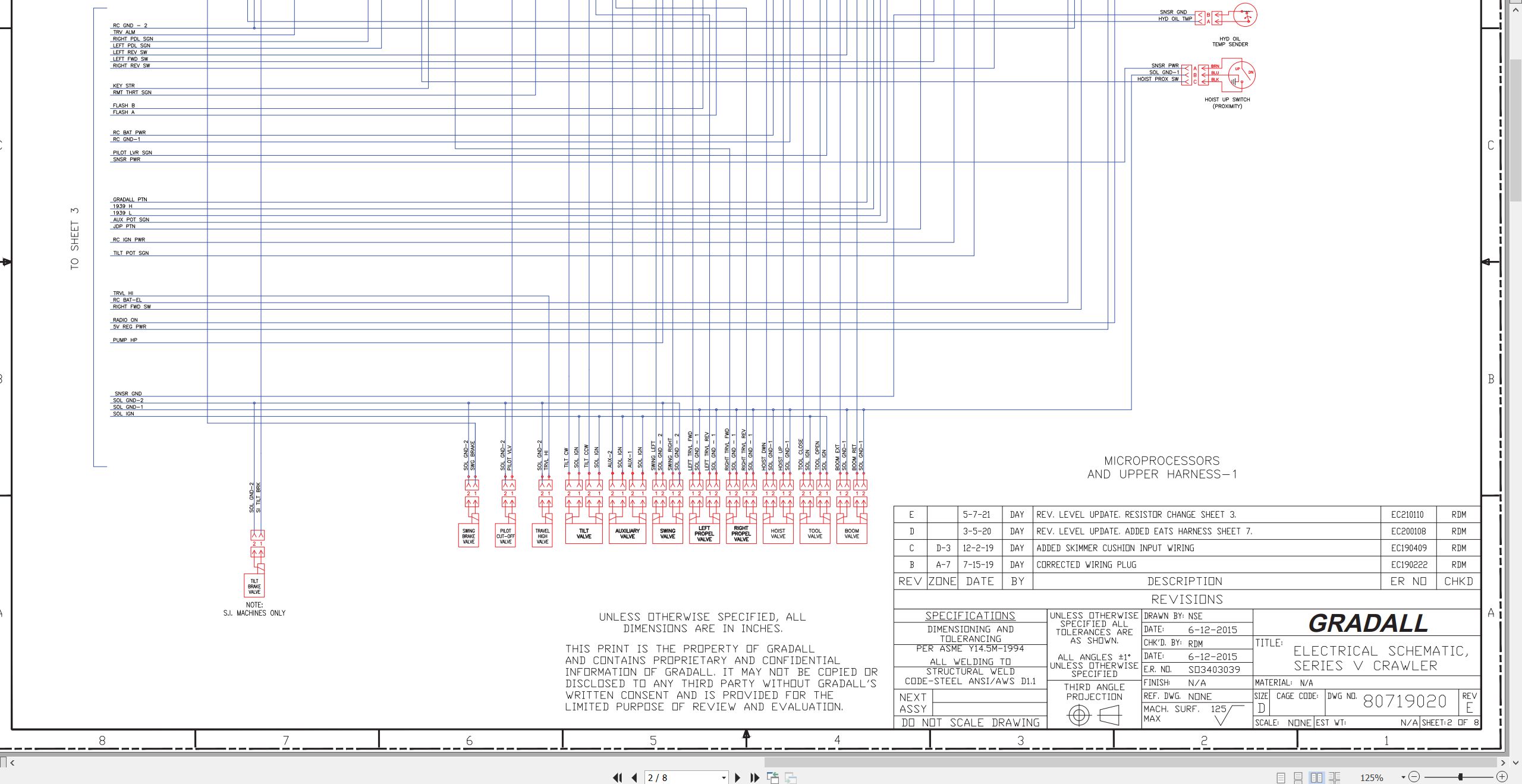
80719020 (E) Electrical Schematic
80763138 (A) Console Circuit Board
80763158 (H) Upper Harness
80763156 (B) Cab Harness
HYDRAULIC
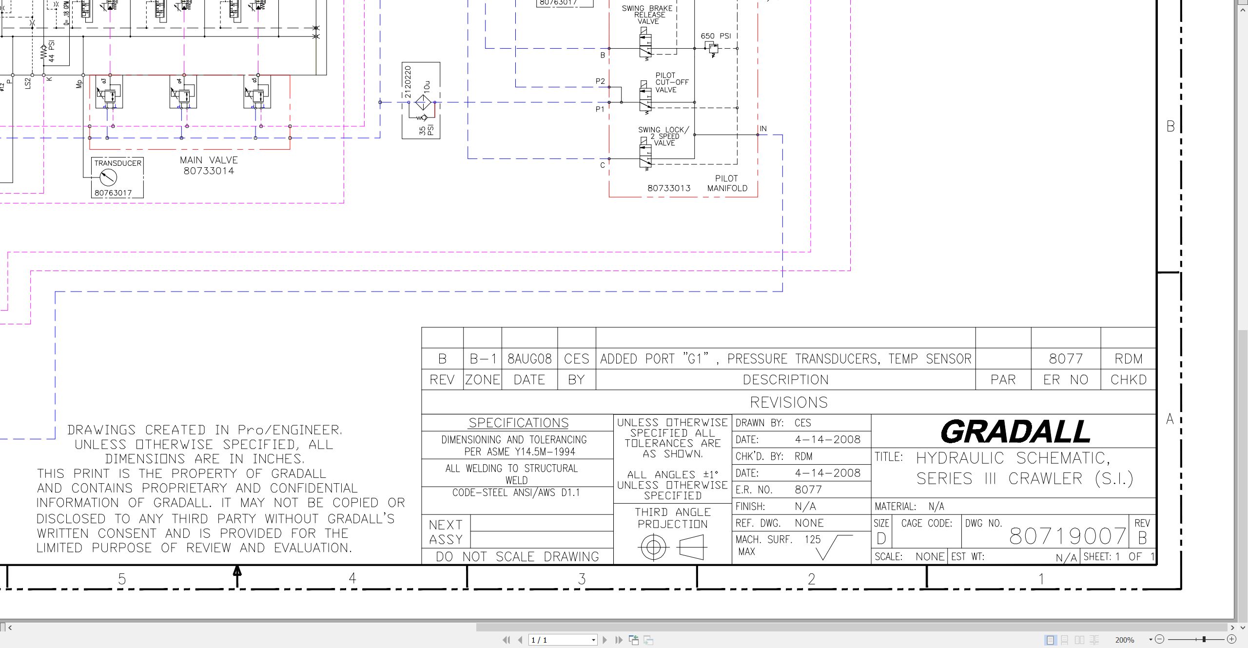
80719022 (-) Hydraulic Schematic
CRAWLER
XL-Series Crawler Maintenance Manual
Introduction
Nomenclature
Track Adjustment
Shoe Contact with Rock Guard
Crawler Travel Speed
Crawler Tracking
Track Chain
Track Rollers
Idler Roller with Track Tension and Adjuster Components
Driver Sprocket
Miscellaneous
XL3210 XL4210 XL5210 Lubrication Chart 80744012.pdf (1 Pages)
SIII Crawler Mount Vendor XL3200 XL3200III to XL4210 XL5200 XL5200III XL5210 Service Literature 2010.pdf (188 Pages)
Contents:
1 About This Manual
1.1 Contents
1.2 Validity Of This Manual
1.3 Important Documents
1.4 Danger Labels And Pictograms
2 Safety
2.1 Basic Safety Information
2.2 Requirements On The Personnel
3 Product Description
3.1 Name Plate
3.2 Functional Description
3.3 Technical Date
4 Exchanging External Assembly Group
4.1 Sealing The Drive Shaft
4.2 Sealing The Control Unit Housing
4.3 Replacing Seals
5 Functional Checks
5.1 Preparations
5.2 Checking The Load Sensing Control
5.3 Checking The Power Control
5.4 Checking The Pressure Control

REALEASE :
REALEASE :

REALEASE :
REALEASE :

REALEASE :
REALEASE :

REALEASE :
REALEASE :

REALEASE :
REALEASE :

REALEASE :
REALEASE :

REALEASE :
REALEASE :

REALEASE :
REALEASE :
 Automotive - Heavy Equipment - Truck & Bus - Forklift - Crane